Showing posts with label rf. Show all posts

Wednesday

Maximizing Throughput on Linux Devices using the RF24 communication Stack

 Maximizing Throughput on Linux Devices using the RF24 communication Stack

How to achieve peak performance via TCP/IP connections

 With the recent changes to the core RF24 driver improving stability, I've begun more thorough investigation & testing regarding max throughput and speed on Linux devices.

 What I've found is that the typical TCP/IP stack for Linux is designed to increase throughput for high speed, bidirectional communication devices, whereas the RF24 Comm Stack is built around the RF24 and RF52 radio devices, which can only either send or receive at a given time. To work around this problem, users are encouraged to modify the TCP/IP window sizes. This allows the system to send smaller payloads, one at a time, thus increasing throughput and overall speed of communication when using the RF24Gateway layers for Linux to Linux device communication.

To configure the window sizes for RF24Gateway, just run the following commands:

sudo sysctl net.ipv4.tcp_wmem="1500 1500 1500"
sudo sysctl net.ipv4.tcp_rmem="1500 1500 1500"

 This sets the window sizes to 1500, which is right around the MAX_PAYLOAD_SIZE configured in the RF24Network layer for Linux devices.

 Results can be tested by running the following commands before and after making this change:

iperf3 -c 10.1.3.134 -4 -t 60 - For no window limit

iperf3 -c 10.1.3.134 -4 -t 60 -w 1500 - With a 1500 byte TCP/IP window

 These changes are only temporary, but users can edit /etc/sysctl.conf to make them permanent.

 Note: These changes can severely impact or disable other network systems & services. Users are advised to put these commands into a script, to enable/disable enhanced RF24 throughput.

 With the RF24Gateway ncurses interrupt example, I'm achieving speeds up to 150-175Kbps or 20-25KB/S over TCP/IP. Up to around 30KB/s using UDP. In order to do this, one needs to modify the line gw.poll(2); and change it to gw.poll(1);. This reduces the delay in the handling of data, allowing maximum throughput.

 IPerf3 results over TCP/IP
 
This works out to around 100-150Kbps on average or 12.5-19KB/s over TCP/IP, which includes the RF24Mesh node renewing its address periodically, interrupting communication slightly. 

 
IPerf3 results over UDP
 
The results with UDP (shown above) vary depending on what bit-rate you set, in this case 130Kbps or about 16.25KB/s was the chosen bit-rate.
 
 
More IPerf3 results over UDP

Here, a slightly higher speed, 145Kbps was chosen, however there was a slight bit of loss. 
(1/14500 Datagrams)
 

RF24Mesh - Dynamic Mesh Networking for NRF24L01+ Radio Modules
An Overview of Progress so Far


Overview:

RF24Mesh is a C++/Arduino/Linux/Raspberry Pi library allowing many devices to simultaneously connect wirelessly and remain connected in a mesh style network using nrf24l01+ radio modules. Nodes can communicate with any other node on the network, including a master node that acts as a gateway for the mesh, providing addressing and lookups.

Once assigned a unique ID, everything is automated, and nodes can move around and rejoin the mesh at any point where another node is in range. RF24Mesh supports some of the smallest and most power efficient devices available.

The RF24 Communication Stack is based on the OSI model, and RF24Mesh makes use of the features of the lower layers (RF24 (Layer 2) , RF24Network (Layer 3), and the overall capabilities can be extended via RF24Ethernet (Layers 4&5 TCP/IP)

Setting it Up:

The main thing when setting up a mesh network is to configure and test your devices accordingly, to make sure they are in a fully operational state. Most if not all of the available radio chips being sold are clones, so I've found it necessary to modify the radio devices slightly in some cases. In many cases, a capacitor (10-100uF) is added directly to the VCC/GND of the module itself to help with common power supply issues.

In the case of these modules, I've found that scraping down the last bit of the antenna, and soldering on a small 3-4" piece of wire greatly improves their performance:
In the case of the high powered PA + LNA modules, I've found it necessary to add shielding as in the post found here. Placing them close to a ground plane seems to help as well. Operating them at a lower power level may be required if the power supply is not adequate.


The modules that are low powered with an antenna generally work out of the box.

I generally recommend using an adapter, to provide a stable power source, even for the low powered modules. I've been using them with many of my modules.

From there it is a matter of installing the Arduino libraries etc. which is covered in the documentation and in earlier blog posts and the official documentation below.

How it works:

RF24Mesh leverages the features provided in the supporting libraries, RF24 and RF24Network to provide connectivity between many devices, even if they are far away from the central node or moving around. Each node is assigned a unique identifier (1-255) and uses that high level-address to request a dynamic address at the network layer, according to the structure of the mesh and proximity to other devices in the mesh. Nodes typically communicate using the RF24Network API, with RF24Mesh working at a higher layer to provide address lookups, dynamic addressing and connectivity.

Nodes arrange themselves using a tree topology around the master node, which provides address lookups etc. for the mesh. At any given time, each node has a path of communication through the network, and can re-establish and verify a new link if the current path fails. In each network there is the master node (the base node), children of the master node (relay nodes) with children nodes themselves, and leaf nodes, (children of the master or its children) with no child nodes attached.

The protocol is fairly simple for each node. On power up or reset, nodes attempt to find a connection by using multicast. Multicasting is arranged into 5 levels, so the master node is contacted first, then its direct children, then their direct children and so on, making the way nodes attach themselves to the network tend towards close proximity to the master node in a tree-like structure. Once contact is made the node requests an address from the master node, either directly or through other nodes. Once an address has been assigned and verified, the node is considered connected to the mesh and can then communicate with all other nodes in the mesh, and beyond to other systems etc.

Nodes have the option of managing their connection however desired, and quite often, a simple timer is suitable to verify connectivity after a set period of time. Transmitting nodes can also detect when communication is failing and re-establish their connectivity to the mesh as required. That is, at any given time, nodes will have a single path to communicate over the network, but if that link fails, they can re-establish their communication path through the network.

The communication layers are interoperable, meaning a network can combine devices running RF24Network and RF24Mesh libraries together, with static nodes running RF24Network, and dynamic nodes running RF24Mesh. Devices running RF24Ethernet (TCP/IP) can also communicate using the other layers of the libraries, interacting directly with RF24Mesh and/or RF24Network nodes. This allows an array of devices to operate on the same wireless mesh network, from ATTiny all the way to the more powerful devices like ESP32 and Raspberry Pi, using the RF24Network, RF24Mesh APIs and/or standard networking tools and protocols. (ICMP/TCP/UDP, etc.)

Current status, testing etc. 

RF24Mesh is now past the development/beta testing stage and considered (by me) to be stable and well tested. The mesh can handle a large number of nodes, theoretically up to 255, but in practice, more like 15-25 nodes sending or receiving data every few seconds is a reasonable bet. It generally depends on the type of traffic and frequency with which it is generated, as a much larger number of nodes reporting data every minute presents only a small load for the network.

The progress made with RF24Mesh is very encouraging, supporting simple communication scenarios, small household sensor networks, home automation systems, and larger expanded networks stretching over relatively long distances with the more powerful RF24 modules.

The RF24 communication stack is generally complete, with bug reports and issues dropping off quite nicely, but development is still ongoing. As always, please report any potential bugs or issues using the GitHub link below. 


Saturday

New Sampling/Audio library for Arduino : AutoAnalogAudio
Easy access to the internal DAC(or PWM), ADC, Timers & DMA for sound generation

I've been playing around with the Arduino Due for a while now, and finally got to looking over the datasheet and playing around with some of the internals because of ongoing requests regarding audio functionality and advanced timer usage etc.

As a result of my dabbling, I've created a sampling library to simplify access to the onboard Analog-to-Digital (ADC), Digital-to-Analog (DAC), Timer and DMA peripherals.

It is a simplified API that allows users to create a wide range of audio or related applications in short order.

Auto Analog Audio (Automatic DAC, ADC & Timer) library

Goals:
Extremely low-latency digital audio recording, playback, communication and relaying using a simple API

Features:
  • New: Now supports AVR devices (Uno,Nano,Mega,etc)
  • Designed with low-latency radio/wireless communication in mind
  • Very simple user interface/API to Arduino DUE DAC, ADC, Timer and DMA
  • PCM/WAV Audio/Analog Data playback using Arduino Due DAC
  • PCM/WAV Audio/Analog Data recording using Arduino Due ADC
  • Onboard timers drive the DAC & ADC automatically
  • Automatic sample rate/timer adjustment based on rate of user-driven data requests/input
  • Uses DMA (Direct Memory Access) to buffer DAC & ADC data
  • ADC & DAC: 8, 10 or 12-bit sampling
  • Single channel or stereo output
  • Multi-channel ADC sampling
  • AVR devices with no DAC or DMA use pseudo DAC(PWM) & DMA(Timer + Memory Buffer)

Testing:

The results so far have been very good. Using the nrf24l01+ radio modules, I was able to stream a standard format *.wav file of high quality (48khz, 16-bit, Stereo) from a Raspberry Pi to the Arduino Due using a slightly modified version of the included Wireless Speaker example.

To put that in perspective: Data Rate = Sample Rate * Channels * BytesPerSample

Streaming over Radio (RF24):
Data Rate = 48,000 * 2 * 2 = 192.0KB/s 

Streaming from SD Card:
Data Rate = 44,100 * 2 * 1 = 88.2KB/s (maximum rate with noticeable slowdown)

Using an SD card is a bit less exciting, as the audio starts to slow down noticeably with audio of 44.1khz, 8-bit, Stereo. Unfortunately, the SD speed is currently a bit limited, since the HSMCI is not available on stock Arduino Due, and I haven't found a faster working library like sdFat for Due.

SdFat Lib:
The sdFat library works with the due, I just had to initialize it at SPI_DIV6_SPEED (10.25Mhz SPI), and it worked using a value of 5 (17mhz SPI) as well. Initial tests show the max read speeds with the stock SD library at about 113KB/s, and 182KB/s with sdFat lib. Adjusting the SdFatConfig.h file to set ARDUINO_FILE_USES_STREAM = 0 results in speeds of 204KB/s with my current card & module.

These numbers indicate that the Due can handle quite a bit of punishment, and is easily up to the task at hand. The main limitation seems to be the throughput of whatever device is providing the audio or recording it etc.

Initial testing on AVR devices seems to indicate functionality similar to my RF24Audio and TMRpcm libraries.

If using a faster device, or generating audio from tables stored in memory, it seems that the Due with the AAAudio library will most likely handle it.

Notes:

If using the RF24 library in combination with an SD card, I highly recommend using a separate SPI BUS for the radio and SD card. I experienced a number of problems with high speed transfers etc when attempting to extend the length of wires used or connect an SD card module as well.

See the SPI_UART library section of the RF24 docs to enable a secondary SPI BUS for the radio.
Due Pins - TX1: MOSI, RX1: MISO, SDA1: SCK, CS&CE: User selected


Installation: AutoAnalogAudio is available via the Arduino Library Manager


I've also included a number of examples that demonstrate usage:
Click: File -> Examples -> AutoAnalogAudio in the Arduino IDE

SDAudio Examples: Demonstrate how to play back and record WAV/PCM format audio from SD card using the AAAudio library

Wireless Examples: Demonstrate receiving and sending streams of audio data via nrf24l01+ radio modules and are easily modified to work with other radios or devices. Some matching examples and audio samples are included for Raspberry Pi.

Audio Generation Examples: Demonstrate playback of simple audio tones or synthesized audio.

ADC/Audio Capture Examples: Demonstrate how to capture data/audio streams from the ADC on one or more pins/channels.

Documentation: http://tmrh20.github.io/AutoAnalogAudio
Source Code: https://github.com/TMRh20/AutoAnalogAudio

Sunday

RF24Gateway - Creating Hybrid IoT Networks using TCP/IP and RF24Network

 RF24Gateway User Interface Example


RF24Gateway is a new complimentary library to RF24Ethernet, designed for RPi and Linux based devices with SPI and GPIO capabilities (BBB, Intel Edison, Galileo, etc).

The RF24Gateway library acts as a network/internet gateway, and allows Arduino/AVR based sensor nodes to interact with each other, the environment, and the world using TCP/IP and/or lower level RF24Network messages.

In short, it allows hybrid IoT networks to be created using Arduino and nrf24l01 modules. Some nodes are capable of internet or local network communication using standard protocols (TCP/IP) and/or RF24Network messages, while other nodes can communicate only at the network level, using only the lower layer RF24Network messaging.

Once RF24Gateway is configured, nodes can be controlled completely using standardized tools and protocols. Additional client examples have been added to demonstrate how to control and/or receive information from sensor nodes using standard tools and scripting methods via Bash, NodeJS and Python scripts. Any method of establishing a TCP connection can be used, with the examples generally using HTTP to some degree as well.

Libraries and code that utilizes RF24Network can utilize RF24Gateway in much the same way, since external data types (TCP/IP) are handled out of sight from the user. RF24Network is used exactly the same way, except that the gateway.update() function is called instead of network.update() or mesh.update(). The included examples demonstrate usage.

Note: RF24Gateway defaults to using a TUN interface with RF24Mesh enabled. RF24Ethernet examples have been updated to accommodate this.

Current Status:

April 2015: Near completion. Integrated fully with RF24Ethernet. Graphical (NCurses) interface example finalized.

Source Code:
https://github.com/TMRh20/RF24Gateway

Documentation:
http://nrf24.github.io/RF24Gateway

Download (See documentation for installation info):
https://github.com/TMRh20/RF24Gateway/archive/master.zip

Monday

Arduino: High Speed (8Mhz) Signaling: NTSC TV Output


I recently purchased a cheap 7" color monitor with intentions of using it for FPV flying, but still have not received the transmitting equipment. Of course, in waiting, I began to wonder about interaction with an Arduino, and a few searches led me to the TVOut library, which achieves NTSC video output (B/W) using an Arduino. I downloaded the library, and the more I read through the code, the more I was intrigued by how exactly such fast and accurate timing was acheived.

To give an idea of the requirements, the horizonal sync signal occurs about 15750 cycles/second (every 63.5us), which is relatively easy for an Arduino to produce in itself. In between these signals however, the picture is drawn, which requires much faster signaling and more precise timing, into the Mhz+ range.

In addition to the TVOut library, I also found a simpler form of code here that uses the USART (Serial port) to form the video signal, using each bit in every byte sent to form individual pixels. The main problem I found with this code was timing. It uses sleep mode to help time the video display accurately, but there were still some issues with small video glitches that I could not resolve when replicating the code. It also uses manual writing of the hsync pulse, where the other method uses a timer generated signal.

The first thing to do was to understand the makeup of an NTSC signal. This page provided a straightforward explanation, along with the timing requirements. Then it was on to recreating a hybrid of the code mentioned above, in the simplest possible format. The first part was pretty straightforward, creating horizontal and vertical sync signals. An entire frame consists of 259 horizontal sync signals, and 3 vertical sync signals, which are simply inverted horizontal sync signals to make 262 lines. The following code will produce a sync signal on pin 12, which results in a blank black screen.


#define hLinesPerFrame  262
#define vSync 247
#define hSync 25

volatile unsigned int isrCounter = 0;

void setup(){
  pinMode(12,OUTPUT);
 

  //This sets up the timer to produce the horizontal sync pulses
  //ICR1 is the timer TOP value, OCR1B controls the hSync pulse width
  //OCR1A will control the timing of the video display
  ICR1 = 1019;

  OCR1A = 1;
  OCR1B = 30;
  TCCR1A =  _BV(WGM11) | _BV(COM1B1) | _BV(COM1B0);
  TCCR1B = _BV(WGM13) | _BV(WGM12) | _BV(CS10);
  TIMSK1 = _BV(OCIE1A); 
}


ISR(TIMER1_COMPA_vect){
  ++isrCounter;

  switch(isrCounter){         
          case vSync: OCR1B = 1019-hSync; break;

          case vSync+3: OCR1B = hSync; break;
          case hLinesPerFrame:  isrCounter = 0; break;
        }
  }


void loop(){ 

}

So that part is easy enough, a few lines of code, a 1k resistor from pin 12, and we have a basic NTSC signal with vertical and horizontal sync. Actually creating video will be a bit more complicated, and I've chosen an Arduino Mega due to the amount of SRAM (8K) available, which is needed for higher resolutions.

What I found in experimenting with different methods for timing, is that the timing of interrupts on a standard Arduino board can vary quite a bit. Using sleep mode to idle the board prior to triggering works 98-99% of the time, but still leaves a few interupts coming a bit late, producing glitches in the video. The method used in the TVOut library appears to work the best, as it monitors the counter to trigger at exactly the same time every time. Of course, it is written in assembly, and I made a slight modification to exit immediatly if the wait time has been missed. My explanation may be a slight bit off technically, but should be pretty close:

static void inline wait_until(uint8_t time) {

__asm__ __volatile__ (
    "sub    %[time], %[tcnt1l]\n\t" //Subtract the low byte of TCNT1 from the wait time
    "brmi   102f\n\t"               //If result is negative, we missed it. Branch to 102

 "100:\n\t"                     
    "subi    %[time], 3\n\t"         //Subtract 3 from time
    "brcc    100b\n\t"               //Loop until we get a negative
    "subi    %[time], 0-3\n\t"       //Add 3 back to our value
    "breq    101f\n\t"               //If equal to 0, branch to 101 and delay 1/16 of a uS (No OPeration)
    "dec    %[time]\n\t"            //Decrement our value by 1
    "breq    102f\n\t"               //If equal to 0, branch to 102 and don't delay
    "rjmp    102f\n"                 //Else Jump to the end
 "101:\n\t"
    "nop\n"
 "102:\n"

     :                                 //Output variables (none)
     : [time] "a" (time),              //Input variables
       [tcnt1l] "a" (TCNT1L)

);
 

}

That takes care of the basic signaling, and provides accurate enough timing to begin looking at displaying the video. I chose to use the USART to draw the video, as it simplifies things quite a bit when compared to using functions written in assembly, and should be able to use a baud rate of 8Mhz in Master SPI mode according to the datasheet. The USART also includes a double-buffering capability, which seems to make it more suitable here than using SPI.


We can calculate our BAUD rate, and the required setting for the UBBRn register at maximum speed:

16Mhz / 2(UBRRn + 1)  -->  16 / 2(0 + 1)  -->  16 / 2 -->  BAUD: 8Mhz  UBRRn: 0

Now, to configure the USART, only two lines of code are required in setup() :

  UCSR1C = _BV(UMSEL01) | _BV(UMSEL00); //Set USART to Master SPI mode
  UBRR1 = 0;                            //Baud rate = 8Mhz


Then to create a buffer for the pixel data of 5400 bytes:
    int totalBytes = (400/8) * 108;   
  byte data[totalBytes];

Now, all there is to do is start drawing pixels at the correct time, which (simplified) is done with the following lines of code, which get added to the TIMER1_COMPA_vector interrupt shown above.

wait_until(153);                      //See the assembly function above

UCSR1B |= _BV(TXEN1);                 //Enable USART TX

for (int x =0; x < 400/8; x++){       //Load bytes until we have drawn 1 horizontal line:
  while ( !(UCSR1A & _BV(UDRE1))){ }  //Wait until the USART is ready for more data
  UDR1 = data[x+start];               //Load a byte
}

  
UCSR1B = 0 ;
                                             //Disable the USART TX


...And thats all there is to it. Of course, the last part of it requires a bit more code to control the screen position and count lines, etc, but those are the fundamentals of producing NTSC video with an Arduino. A complete sketch is posted below.

Notes:
a: The timing of the video display in relation to the horizontal sync pulse is very important. It specifically triggers before the h-sync pulse ends so as to have enough time to smooth out variations in triggering.
b: The loading of data into the buffer (UDR1) must be done as quickly as possible, and requires efficient code to work at 8Mhz.
c: Using the USART requires accurate screen positioning due to the pulse created whenever it is enabled. This creates a vertical line, which can be positioned off screen via the wait timing.
d: This code does not use the defined standard timing for parts of the signal, due to better results with slightly modified settings. (ie: 2uS horizontal pulse instead of 4.7uS)
e: The maximum resolution is mainly limited by the memory available, as 1 byte is required for every 8 pixels. (400 x 108 uses 5.4KB)

Summary:
For me, this was an interesting look at the maximum limitations of signaling using an Arduino, and gave me an opportunity to learn a little more about assembly code as well. I found a great tutorial here showing how to view your Arduino code in assembly, and it was a great help in beginning to understand the code behind the code.
All in all, I am pretty happy with the results, as the methods used above seem pretty comparable to the TVOut libary, but with a bit higher resolution. The main benefits of using the USART are simplified code, as the baud rate can be changed to scale the video horizontally, and feeding it data is very straightforward.

The code used to create the above video can be found here and borrows heavily from the code it is based on.


Wednesday

Custom Arduino QuadCopter: First Outdoor Test Flights

I've finally had some opportunities to do some outdoor testing, and this is the first such test with a GoPro camera attached. The quad is running on a stock Arduino Mega2560 board, along with some sensors and a digital transceiver. Details of the build are documented here and in previous posts.

This is the first recorded outdoor test-flight, and it goes pretty well at first with some easy flying. I end up trying to do spins and flying around while forgetting to switch from MAG to HeadFree mode, so lose control at the end.

The ESCs are not sealed well from moisture, so needed to be dried out after the snow landing.

The following video is from a 30,000sq ft indoor fly event hosted by Regina Micro-Flyers at the CU EventPlex April 7, 2013:


Tuesday

Digital Data Encoding: Manchester, BMC and Frequency Modulation(FM)

Data generally needs to be encoded to enable the transmission of digital data across various mediums, and I've always had an interest in radio/wireless communication, so this was pretty much going to happen eventually. I've used some VirtualWire modules, and took an interest in how they work and how to apply the concepts learned from that code and other sources. This lead to the following sketches which encode data using a modified version of Biphase Mark Code (BMC) encoding, which is a specific form of Frequency Modulation, (FM) used to transfer digital data.


A Quick Look at BMC Encoding:

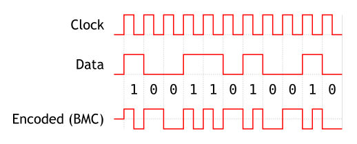
If you look up Biphase Mark Code online, you may be lead to information on Differential Manchester encoding, which has fundamental differences from BMC. You will also generally find excessively complex explanations of how it works, but it is actually quite simple. In the end, you basically send a bunch of binary data (1 and 0), and represent that data either with 1 long period or 2 short periods:

ie: 1 = Long, 0 = short,short  OR  0 = Long, 1 = short,short

The important factor is the length of time between transitions (The point at which the wave transitions from high to low or low to high). This image from wikipedia shows how the data is encoded into a wave:


How does it work?

This code is derived from concepts described here and in the VirtualWire Arduino library. The VirtualWire library appears to use a sampling based decode method and '4-to-6 bit' encoding of the data prior to transmission. Comparativly this was more of a learning exercise than a useful project, so is fairly simple, and uses timer based encoding.

Arduino Uno,Mega etc have an 'Input Capture' function that can trigger an interrupt and timestamp it, and I was interested in trying it out for this type of digital communication. This code uses that capability to calculate the difference between transitions and thus decode the binary data. Timer1 is used as a counter to provide the timestamp for the receiver, and used to generate the proper waveform for the transmitter.


Results:

I started off initially using Differential Manchester encoding, and was able to acheive ok results for wireless transmission. The results weren't very useable initially, so I tested a few different methods of modulation, ending up with BMC encoding producing the best results. BMC uses two small transitions for one bit, and one large for the other (0 or 1), so I tried it with only a single small transition, and seem to have the best results so far. I'm not sure if this fits in with another modulation technique, but it is FM either way.

Transmitter:

The data being sent is broken into bits and buffered into memory, while Timer1 is configured to run at a set frequency. A full pulse width is created to encode a 0, and a half pulse width is created to encode a 1, modulating the frequency to send data. The compare-output mode is toggled every cycle to produce the correct waveform, ensuring that positve pulses always follow negative pulses and vice-versa. 

Receiver:

The receiver uses the built-in Input Capture mode to timestamp the high and low transitions of the pulses being received, then calculates whether a 0 or 1 was received based on the timestamp. As the bits are received, they are loaded into a temporary byte. If that byte is equal to the 'start byte', it starts buffering data and looks for a 'stop byte'. Once received, it does a simple CRC check to ensure the data is not corrupt, and then makes the data available if successful.


Arduino Sketches:

 This seems to work well in testing, up to 32Kbps with a direct connection, and up to 7Kbps at close range with some very cheap 433Mhz VirtualWire capable modules I had sitting around. This was a pretty interesting task, and a good way to understand the general concepts behind the raw signaling that digital devices use to communicate. This is about as far as I plan to take this code for now, so I threw in a bunch of comment  s:

RX (receiver)  (Timer4, Pin 49 on Mega)
TX (transmitter) (Timer1, Pin9 on Uno,Nano,etc)


QuadCopter: Current Summary, Docs and Info 


The quad, controller, and camera


Flight Control Board

The flight control board is based on FreeIMU and built onto an Arduino Mega 2560 running MultiWii. The main goals were to build a customizeable and affordable quadcopter using mainly open source hardware and software, and learn a bit about how it all works. Bugs and design issues seem to have been worked out now, so it looks like this will be the base design for my board. Video

Since it is all open source, adding additional custom components to control lights, sound, servos, etc. is about as easy as it gets. For anybody already familiar with Arduino, it's just a matter of  choosing what customizations to add.

The top picture on the right shows the simplicity of  the FC board, using only a few modules. A previous mock-up of the board was scrapped due to some simple design flaws. The current version attempts to address some of those problems:

a: Although the shield fits tight, secure mounting is a must, and nylon standoffs are used to secure the shield to the Arduino.

b: Here I am using a cheap, single sided prototyping board, but we'll see how long it lasts...

c: The first mock-up used the female header pins as shown on the right of the bottom pic, but they aren't made for Arduinos (too thin), and caused I2C errors and subsequent crashes. The header pins shown on the left are thicker and fit snug every time.

d: The GPS module was left out since GPS nav won't be something I'll be using right away.

The ESCs connect to pins exposed on the top of the board, which are hard to see since the angle of the bottom pic purposely hides my shoddy looking soldering work. The Arduino gets fastened to the frame using rubber mounts taken from broken CD/DVD players to minimize vibration.


Notes:

FC Board:
The board is intially based on a FreeIMU board as mentioned previously, and is actually pretty simple to build at this point, with only 3 modules. The HMC5883L magnetometer module is connected to the aux. I2C lines of the MPU-6050, and running on 3.3V. An APC220 module is connected to the fourth serial port (serial3), and a GPS module can go on serial2 or via I2C if desired. The best part of the flight controller and quadcopter is that it is all based on open source software and hardware, so customization and prototyping like this is actually possible without spending huge amounts of money or time.

FC Board/Arduino Mega Connections:
pin2: front motor
pin3: rear motor
pin5: right motor
pin6: left motor
pin14: APC220 RX pin
pin15: APC220 TX pin
pin16: GPS RX pin
pin17: GPS TX pin
pin18: MPU6050 interrupt
pin20: MPU6050 SDA (I2C)
pin21: MPU6050 SDL (I2C)
pinA0: Voltage divider (battery monitor)
MPU6050: Aux SDA to HMC5883L SDA
MPU6050: Aux SDL to HMC5883L SDL


Main Parts:
1x Turnigy Talon carbon fiber frame
4x Turnigy 20Amp MultiStar ESCs
1x Turnigy ESC programmer
4x NTM Prop Drive Series 28-26A 1200kv/250W Motors
2x Slow Fly 8045 propellers
2x Slow Fly 8045R propellers
1x 4000mAh 3S LiPo battery pack
1x Arduino Mega
1x GY-521 Gyro Module (MPU-6050
1x HMC5883L Magnetometer module 
1x APC220 serial data wireless transceiver
Uses Modified XBox controller for RC (previous post)


XBox Controller:
Prev post. Uses the MultiWii RCSerial protocol
Quad can easily be controled by a PC via RCSerial protocol and APC220 transceiver

Frame/Physical Assembly:

Since the controller and FC board are both custom made, I had to code and then debug the controller during flight in some cases, and had no failsafe at the time. The initial assembly of the central parts of the frame used all nylon bolts. This was to prevent damage to the frame and motors when big crashes happened, since parts would usually break away before breaking or bending much. It currently uses a combination of metal and nylon connectors to provide rigidity and allow for some give on big impacts. As can be seen in the picture above, I have also made my own motor mounts.

ESC Calibration:

One of the problems I ran into in some of the first flights was individual motors cutting out seemingly randomly. The quad uses 20A Turnigy MultiStar ESCs, and gives a choice between slow-down of motors, and hard cutoff when the voltage is low. This caused a bit of frustration since the motors would start cutting out when the voltage was low, regardless of the setting via programming card.

I was confused by the MultiWii calibration code at first since, according to the ESC manual, it would basically just set the programming of the ESCs to the LiPo battery setting, and that hardly seemed like 'calibration':

ESC Programming:
a: Power ESCs on while receiving max throttle signal
b: These ESC will beep accordingly, move throttle to min to select what option to set in the programming 

The ESCs apparently use this interaction for calibration as well, and it made a big difference once I programmed them this way. The motors seemed to sound a bit smoother afterward, and they slow down nicely to force a landing once the battery is low.

Always remove your propellers before uncommenting this line in 'config.h':
#define ESC_CALIB_CANNOT_FLY 

Propeller Balancing:

Another important factor that was initially overlooked was propeller balancing. This made a big difference in the stability of the craft, as well as reducing vibrations. I followed this tutorial and had some good results on my first shot at it. Videos from the previous post show the vibration evident from unbalanced propellers, and a motor wire breaks in the second one, likely related to the vibration issues.

MultiWii Config and GUI:

The videos in the previous post were shot using the PID settings shown in the pic to the right and with the low-pass filter enabled for the MPU-6050 at 20Hz in 'config.h'. Higher values for the filter makes for 'tighter' controls, but is more susceptible to vibration and affects PID. Mitigating vibration issues should allow a higher setting. 

MultiWii Code:
Code base is MultiWii_dev_r1240
Uses slightly modified version, but can work with original:
  • Supports serial rc cmds with smaller payloads
  • Supports failsafe when using serial rc
  • Supports basic monitoring during flight via processing gui and existing transceiver (prev. post)
  • Still unsure whether to remove or work with test code to control a music player from alarms and controls, so left it in for now (alarm buzzer timing is changed)
  • Longer delay for ESC calibration code specific to MultiStar ESCs (see esc manual below)


Reference Material:
MultiWii - Code w/Modifications
MultiWii - Arduino Mega pin layout
MultiWii Wiki


Saturday

Quad/GoPro Camera Test

This video shows one of the first test flights using a GoPro camera strapped to my quadcopter. The camera is mounted using the included straps and is free to move around a little bit, so there is some movement and vibration evident in the video. Although way off balance, stability and power aren't much of a problem, but the batteries drain noticeably faster with the camera attached. The throtte is being hard limited to 75% for indoor testing.

Here the camera swings a lot so the video can be hard to watch:

Here the camera is mounted in a more stable way, top-side:


Sunday

Quad-Copter: Free at last

The quad has come a long way in a short time since the previous post. After a fair bit of reading, adjusting and testing, I was finally able to get my custom flight control board working with the MultiWii software, and the initial results are better than expected.

I was able to get it working initially with the flight software by converting the data to PPM Sum at the receiver, and it worked fairly well in testing. This required the use of an additional microcontroller to receive the signal and convert it, so was not ideal.
Below is a short video showing the Quad-Copter while I attempt to learn the controls and work out some of the details on my custom controller. There are many things that still have to be tweaked, tuned, adjusted, and implemented but at this point, it is looking pretty promising for a custom rig:


After some more looking at the RCSerial protocol built into MultiWii, I was able to build it into my sketch and communicate directly with the flight control board using serial data via APC220 radio module, and my customized XBox controller. I had some troubles finding examples of direct control using the RCSerial protocol, so here is the working but incomplete sketch I have been using. In the next video, the flight control board is closer to completion, with the rf module, gyro/accel and magnetometer all soldered into place, and is using the 'Angle' and 'Mag' modes in MultiWii:


This mode is a lot easier to fly in, and after a few more flights like this, I'm comfortable that this setup is going to work pretty well, especially after some tuning and adjustments. As can be seen, the motor mountings are bent a bit, and the propellers also have some big cracks in them due to previous crashes, but it flies fairly well regardless. The throttle is being hard limited to 3/4 just for safety indoors, and I'm not getting close, so it will be interesting once this thing is outside. Additional features like low battery detection needs to be added, and some extras like GPS, a barometer, or an LCD screen may be added too, but a few bugs need to be worked out first. And yes, that is in fact a breadboard plugged into the Arduino Mega like a shield in the first video.


Details of flight controller on Summary Page:


Tuesday

Building a Quad-Copter

Why a quad-copter? Time spent working on various projects involving robotics and automation have led me to a single conclusion: Flying Robots!

My first searches on the subject turned up various projects that offer pre-built units you can simply buy, connect, and fly, but the point here is to build a unit with interchangeable and customizeable Arduino-based flight and radio controls, and hopefully learn a few things along the way. This will also allow me to build, tweak, add or modify any component as required.

After receiving the main components: frame, motors, ESCs, battery, etc., the first thing I did was test out a single motor and ESC using DIY speed control (An Arduino). I have some 20A Turnigy MultiStar ESCs, so connected the orange wire to pin 9, brown to ground, and left red unconnected. Then, with the power connected to the battery, and using the servo library, I was able to get the motor going by using servo.writeMicroseconds(700); and ramping it up to about 800 to hear the beep indicating it is ready to go, and then up to 900 to get the motor turning. Ramping it up higher increases the RPM, so it seems pretty simple to control. Later experimentation showed that starting at 1000 and ramping up from there seems to work the best.

Setup for spinning motors up and first liftoff:

The initial testing was done using commands sent over the serial port, and the next step was to use wireless remote control so, of course, I used the newly customized XBox controller from the previous post to acheive that. The controller sends a variable and/or a value, (such as "S 1000" for a speed of 1000) and reception is as simple as Serial.read(); etc. Since there are multiple rotors, two must spin the opposite direction of the other two, along with having reversed propellers. The ESCs come with a simple programmer, so direction is easily controllable electronically. Along with the servo library, I was able to spin up all four motors and get the quad-copter airbourne for the first time, if just for a few seconds.

Next is final assembly of the unit and to try for some DIY flight stabilization. My first attempts at flight control will use the Proportional-Integral-Derivative (PID) library which takes an input (pitch,roll, etc) and adjusts an output (motor speed) to maintain a constant reading. This is the same type of thing the line-following-junkbot code attempted to do. Currently, I have an MPU-6050 gyro/accellerometer module connected, which I hope is enough for some simple stabilization. Prior testing required the device to be strapped to the floor with a few inchess of slack, just enough for it to get airbourne, and the same setup will be used here. As luck would have it, my frame kit is lacking in nuts and bolts, so I had to scrounge some up from various broken electronics, and the "feet" are not connected.

First stabilization attempt

Above is the video showing the initial flight using untested and untweaked settings for the PID library and stabilization. Without PID enabled, the quadcopter lurches and jumps when the ropes pull tight, so this flight demonstrates that the stabilization is at least somewhat effective. Next will be to tweak and tune the PID, timing, and associated code for more stable flight, then probably on to controlling its movement.

This next video shows the quad once the PID settings are tuned a little bit better, as it demonstrates some actual stability. It is connected to the board via a large elastic, so whenever it pulls taught suddenly, there is a tendancy to jerk to the side, which the copter succesfully counteracts to a large degree. It took a fair bit of work to acheive this much stability, so a pre-bought flight control board is starting to look appealing.

More progress towards stabilization

Judging by its stability when under load and encountering some additional outside forces (from the tether), it may be time to start working on movement controls. They would simply adjust the balance point for the yaw and pitch, allowing me to direct its movements, and do some more fine tuning on the PID adjustements.

The MPU-6050 will be used in conjunction with an HMC5883L, which pretty much gives me the equivalent of the FreeIMU v0.4 board, minus the barometer. I've run the FreeImu GUI software, and succesfully calibrated my device, but the MPU-6050 library below seems to provide much more accurate readings, so I've been sticking with that. Since it works fine with the FreeIMU library, I attempted to use the MultiWii libraries, but have not had any luck. The sketch below is pretty basic, and only uses yaw, pitch, and roll readings for stabilization.


Libraries and Sketch:

Rough sketch
MPU-6050 library
Modified PID library


Hardware info on Summary Page


Saturday


                   Original Box Controller: Arduino-based Wireless RC Conversion V2

Here are the details of my second conversion of an original XBox controller into a wireless controller for Arduino-based devices. I chose an XBox controller since it offers a well designed unit for little to no cost, replacement parts are easy to find, and it offers many inputs in the form of buttons, triggers, and joysticks. I chose an old controller that stood up well in its day and is about the same size and shape of a current XBox360 controller. Info and code regarding the first iteration of this can be found here and here.

This version will be similar to the first with a few differences:
a: Now using a UART driven radio module. Rx/Tx is as easy as using Serial.read/write. Fairly long range: 1000m
b: Wiring is simplified by using internal pullup resistors for every digital input
c: Better design of wiring and layout.
Other design considerations/options:
- Arduino Mini seems better suited, but did not have one on hand.
- If use is 'static' and predetermined, microcontroller can be completely embedded with a DIY board.

Below are the detailed steps showing the installation of an Arduino Nano into the controller along with an APC220 radio module. 

Pics:
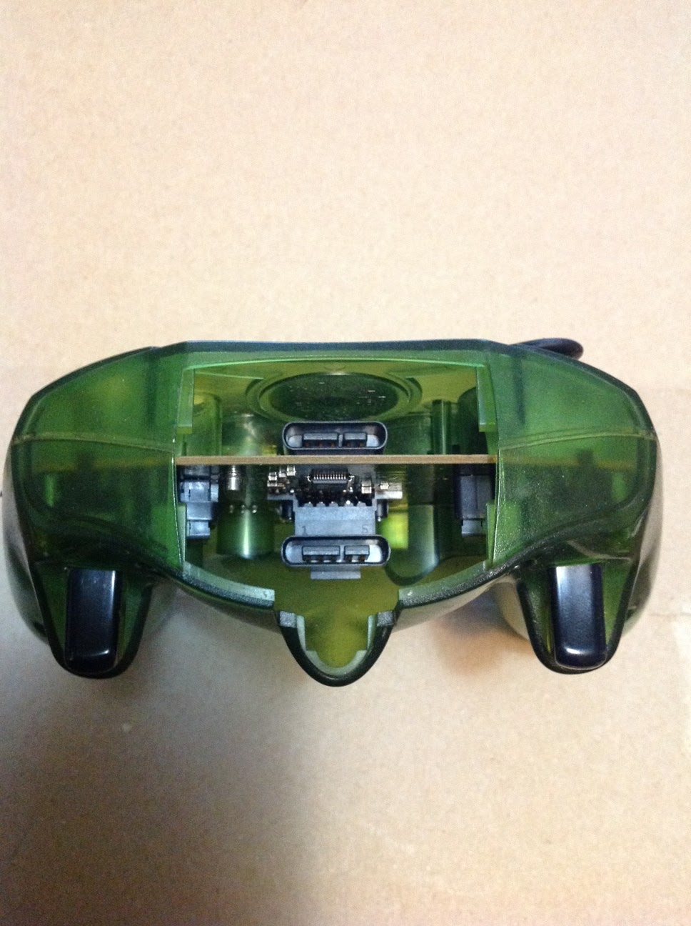
The XBox controller as original and opened for the first time. This just required the removal of some screws and a sticker.


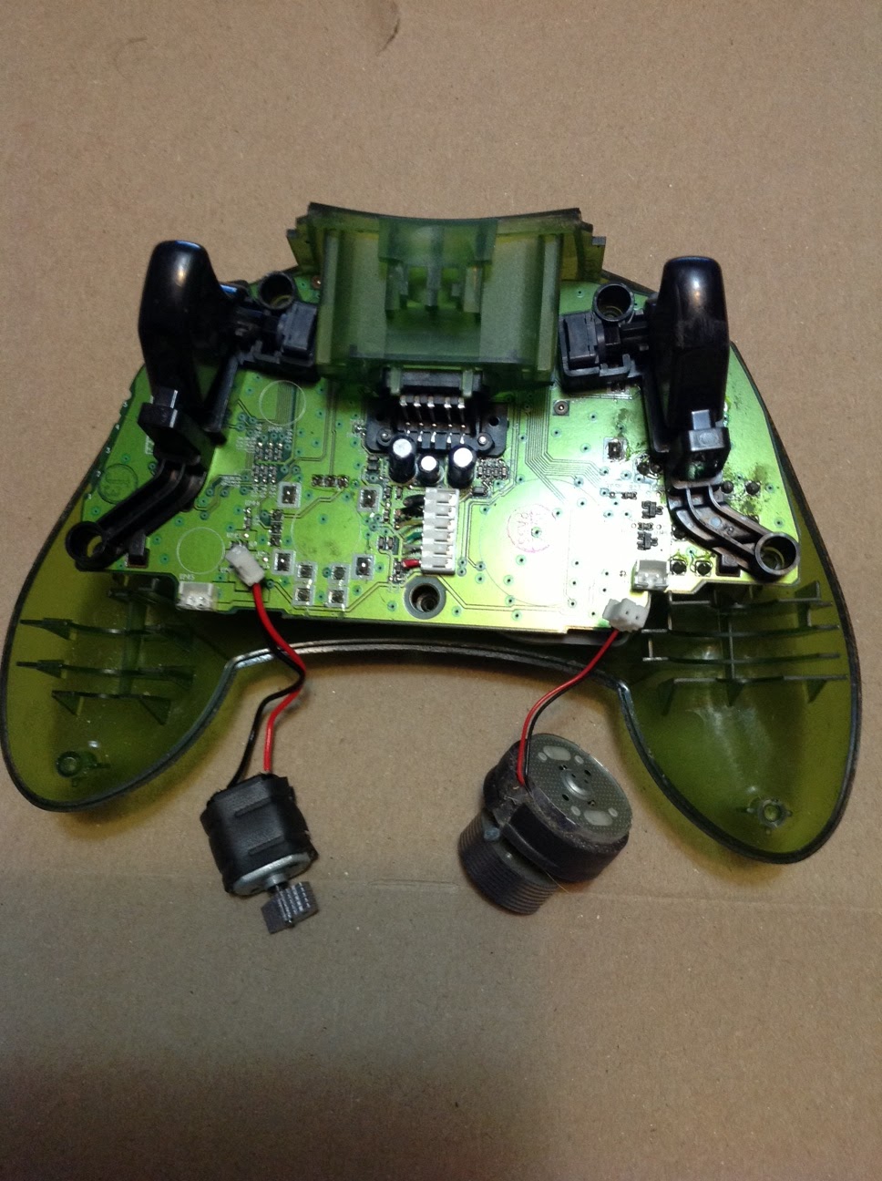
A look at the insides with the cable cut away and close-ups of joystick and potentiometer that will provide an analog reading to the Arduino.


A closer look at the insides of the controller before and after removing the big plastic center piece.


The center black piece required a soldering iron to remove. Plenty of room to work after removal:


The method I used to cut the circuit board was to grind or cut through most of the copper layers with a knife or rotary tool, then I cut through the remaining part with scissors. Without piercing the copper, it kind of shatters when cut. Shots of the board with center piece cut away. As seen in the right side picture below, could have more easily connected the wires to the group of solder points instead since there is one for each button after removing the smd resistors.


Now to finish wiring it up. The controller has a total of 14 digital outputs (buttons/d-pad) and 6 analog outputs (potentiometers/joysticks), and I will be using all of them except the buttons attached to the joysticks. The pictures show how it is wired up in reality, and in theory, the buttons are wired as shown here while joysticks/triggers are as shown here. Some descriptive info can be found in a prev post here. The idea is to cut out or grind away any connections leading from the + side of the buttons and potentiometers, then run your own wires in their place. In this case, the pots on each side shared a common positive lead, so I left that in place. Removing the triggers was necessary to get at all the leads.


Final pics showing the assembly of the modified controller. A small part of the inside case had to be ground away to make room for the wires to be run underneath it The board with the arduino and RF module attached was also ground down a bit in a few places to make it fit inside the controller a bit tighter, as shown in the last picture.


The output from a simple test sketch displays the 12 digital and 6 analog readings. Despite my less than skillful soldering work, all readings are testing correctly except those from the the B and X buttons, which were not responding at first, but turned out to be due to loose connections. Not too bad for the initial powerup!


The next step was to transmit the data, which ends up looking exactly the same when sent over the radio link to the PC or an Arduino. Then the top cover piece was modified as shown to make room for the ends of the electronics and to fit the battery inside. I will probably make room for the battery to slide back farther, but it fits nice and snug, so will leave it for now


Troubleshooting and Details:
- Test for short circuited connections after soldering a large number of wires, and before powering up for the first time. Small wires being heated tend to melt together.
- Seems best to secure the wires to the board since they need to run through certain paths in the case, and it helps to prevent wires from coming loose or being mangled. A small grinding tool helps to make room.
- A multimeter is essential for finding the correct leads and troubleshooting 
- Interfacing to the existing USB connection may be possible with a USB host shield, but that would add additional hardware, size and cost.
- The parts etc. were all chosen for simplicity, but more customization could make a nicer integration.
- I tried to avoid using the software serial library via the method described here, but went back to it due to what seemed like buggy behaviour.

Main Required Parts for Build:
1x Arduino Nano
2x Serial-data RF Module (APC220 or other)
1x Original Xbox controller 

Connections/Pins (Arduino Nano):
2-10:  Buttons ABXY, UDLR, black
A0,A1 - R JoyStick U/D,R/L
A2,A3 - L JoyStick U/D,R/L
A4,A5 - Buttons Start,Select
A6,A7 - Triggers R,L
12 - APC220 SET pin
11 - APC220 Serial RX pin 

Arduino Sketch:
Found here. The sketch is designed for controlling MultiWii based devices via the built-in RCSerial protocol.
Note: Sleeps after 5 seconds of inactivity. Press A to wake up.


Creating a Customized Zephyr Project + Arduino core

 Creating a Customized Zephyr Project + Arduino core Working outside them boxes   I currently have 2 Arduino Uno Q boards in my possession, ...