Original Box Controller: Arduino-based Wireless RC Conversion V2
Here are the details of my second conversion of an original XBox controller into a wireless controller for Arduino-based devices. I chose an XBox controller since it offers a well designed unit for little to no cost, replacement parts are easy to find, and it offers many inputs in the form of buttons, triggers, and joysticks. I chose an old controller that stood up well in its day and is about the same size and shape of a current XBox360 controller. Info and code regarding the first iteration of this can be found here and here.
This version will be similar to the first with a few differences:
a: Now using a UART driven radio module. Rx/Tx is as easy as using Serial.read/write. Fairly long range: 1000m
b: Wiring is simplified by using internal pullup resistors for every digital input
c: Better design of wiring and layout.
Other design considerations/options:
- Arduino Mini seems better suited, but did not have one on hand.
- If use is 'static' and predetermined, microcontroller can be completely embedded with a DIY board.
Below are the detailed steps showing the installation of an Arduino Nano into the controller along with an APC220 radio module.
Pics:
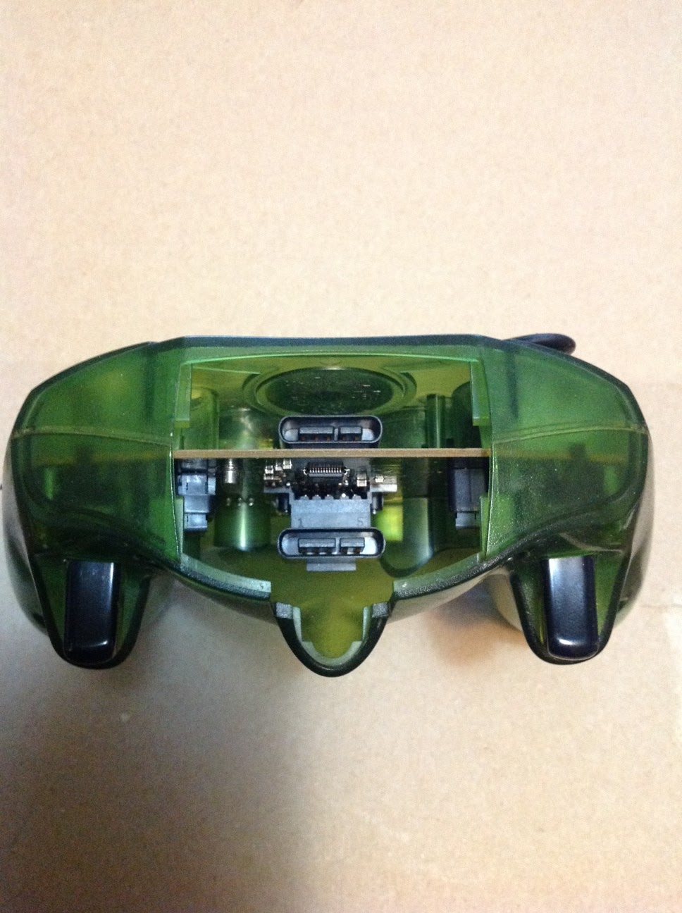
The XBox controller as original and opened for the first time. This just required the removal of some screws and a sticker.


A look at the insides with the cable cut away and close-ups of joystick and potentiometer that will provide an analog reading to the Arduino.
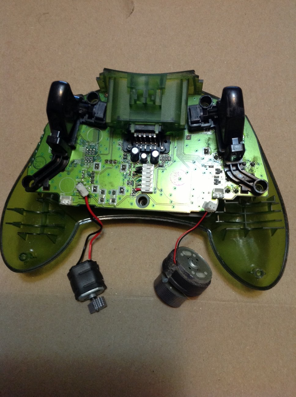


A closer look at the insides of the controller before and after removing the big plastic center piece.


The center black piece required a soldering iron to remove. Plenty of room to work after removal:


The method I used to cut the circuit board was to grind or cut through most of the copper layers with a knife or rotary tool, then I cut through the remaining part with scissors. Without piercing the copper, it kind of shatters when cut. Shots of the board with center piece cut away. As seen in the right side picture below, could have more easily connected the wires to the group of solder points instead since there is one for each button after removing the smd resistors.


Now to finish wiring it up. The controller has a total of 14 digital outputs (buttons/d-pad) and 6 analog outputs (potentiometers/joysticks), and I will be using all of them except the buttons attached to the joysticks. The pictures show how it is wired up in reality, and in theory, the buttons are wired as shown here while joysticks/triggers are as shown here. Some descriptive info can be found in a prev post here. The idea is to cut out or grind away any connections leading from the + side of the buttons and potentiometers, then run your own wires in their place. In this case, the pots on each side shared a common positive lead, so I left that in place. Removing the triggers was necessary to get at all the leads.


Final pics showing the assembly of the modified controller. A small part of the inside case had to be ground away to make room for the wires to be run underneath it The board with the arduino and RF module attached was also ground down a bit in a few places to make it fit inside the controller a bit tighter, as shown in the last picture.


The output from a simple test sketch displays the 12 digital and 6 analog readings. Despite my less than skillful soldering work, all readings are testing correctly except those from the the B and X buttons, which were not responding at first, but turned out to be due to loose connections. Not too bad for the initial powerup!

The next step was to transmit the data, which ends up looking exactly the same when sent over the radio link to the PC or an Arduino. Then the top cover piece was modified as shown to make room for the ends of the electronics and to fit the battery inside. I will probably make room for the battery to slide back farther, but it fits nice and snug, so will leave it for now


Troubleshooting and Details:
- Test for short circuited connections after soldering a large number of wires, and before powering up for the first time. Small wires being heated tend to melt together.
- Seems best to secure the wires to the board since they need to run through certain paths in the case, and it helps to prevent wires from coming loose or being mangled. A small grinding tool helps to make room.
- A multimeter is essential for finding the correct leads and troubleshooting
- Interfacing to the existing USB connection may be possible with a USB host shield, but that would add additional hardware, size and cost.
- The parts etc. were all chosen for simplicity, but more customization could make a nicer integration.
- I tried to avoid using the software serial library via the method described here, but went back to it due to what seemed like buggy behaviour.
Main Required Parts for Build:
1x Arduino Nano
2x Serial-data RF Module (APC220 or other)
1x Original Xbox controller
Connections/Pins (Arduino Nano):
2-10: Buttons ABXY, UDLR, black
A0,A1 - R JoyStick U/D,R/L
A2,A3 - L JoyStick U/D,R/L
A4,A5 - Buttons Start,Select
A6,A7 - Triggers R,L
12 - APC220 SET pin
11 - APC220 Serial RX pin
Arduino Sketch:
Found here. The sketch is designed for controlling MultiWii based devices via the built-in RCSerial protocol.
Note: Sleeps after 5 seconds of inactivity. Press A to wake up.


No comments:
Post a Comment