Saturday


                   Original Box Controller: Arduino-based Wireless RC Conversion V2

Here are the details of my second conversion of an original XBox controller into a wireless controller for Arduino-based devices. I chose an XBox controller since it offers a well designed unit for little to no cost, replacement parts are easy to find, and it offers many inputs in the form of buttons, triggers, and joysticks. I chose an old controller that stood up well in its day and is about the same size and shape of a current XBox360 controller. Info and code regarding the first iteration of this can be found here and here.

This version will be similar to the first with a few differences:
a: Now using a UART driven radio module. Rx/Tx is as easy as using Serial.read/write. Fairly long range: 1000m
b: Wiring is simplified by using internal pullup resistors for every digital input
c: Better design of wiring and layout.
Other design considerations/options:
- Arduino Mini seems better suited, but did not have one on hand.
- If use is 'static' and predetermined, microcontroller can be completely embedded with a DIY board.

Below are the detailed steps showing the installation of an Arduino Nano into the controller along with an APC220 radio module. 

Pics:
The XBox controller as original and opened for the first time. This just required the removal of some screws and a sticker.


A look at the insides with the cable cut away and close-ups of joystick and potentiometer that will provide an analog reading to the Arduino.
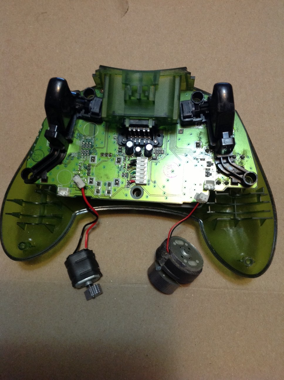

A closer look at the insides of the controller before and after removing the big plastic center piece.


The center black piece required a soldering iron to remove. Plenty of room to work after removal:


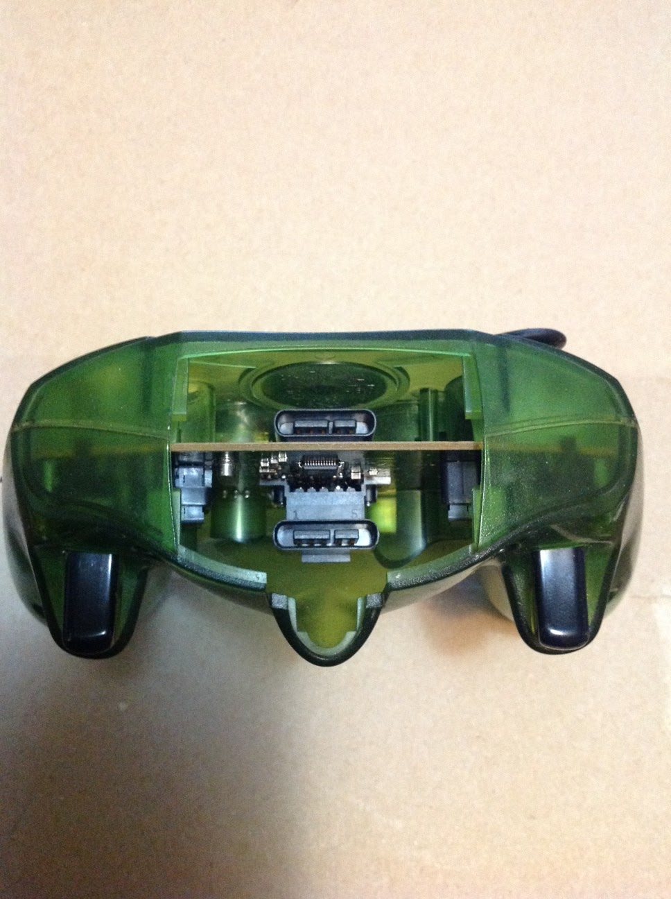
The method I used to cut the circuit board was to grind or cut through most of the copper layers with a knife or rotary tool, then I cut through the remaining part with scissors. Without piercing the copper, it kind of shatters when cut. Shots of the board with center piece cut away. As seen in the right side picture below, could have more easily connected the wires to the group of solder points instead since there is one for each button after removing the smd resistors.


Now to finish wiring it up. The controller has a total of 14 digital outputs (buttons/d-pad) and 6 analog outputs (potentiometers/joysticks), and I will be using all of them except the buttons attached to the joysticks. The pictures show how it is wired up in reality, and in theory, the buttons are wired as shown here while joysticks/triggers are as shown here. Some descriptive info can be found in a prev post here. The idea is to cut out or grind away any connections leading from the + side of the buttons and potentiometers, then run your own wires in their place. In this case, the pots on each side shared a common positive lead, so I left that in place. Removing the triggers was necessary to get at all the leads.


Final pics showing the assembly of the modified controller. A small part of the inside case had to be ground away to make room for the wires to be run underneath it The board with the arduino and RF module attached was also ground down a bit in a few places to make it fit inside the controller a bit tighter, as shown in the last picture.


The output from a simple test sketch displays the 12 digital and 6 analog readings. Despite my less than skillful soldering work, all readings are testing correctly except those from the the B and X buttons, which were not responding at first, but turned out to be due to loose connections. Not too bad for the initial powerup!


The next step was to transmit the data, which ends up looking exactly the same when sent over the radio link to the PC or an Arduino. Then the top cover piece was modified as shown to make room for the ends of the electronics and to fit the battery inside. I will probably make room for the battery to slide back farther, but it fits nice and snug, so will leave it for now


Troubleshooting and Details:
- Test for short circuited connections after soldering a large number of wires, and before powering up for the first time. Small wires being heated tend to melt together.
- Seems best to secure the wires to the board since they need to run through certain paths in the case, and it helps to prevent wires from coming loose or being mangled. A small grinding tool helps to make room.
- A multimeter is essential for finding the correct leads and troubleshooting 
- Interfacing to the existing USB connection may be possible with a USB host shield, but that would add additional hardware, size and cost.
- The parts etc. were all chosen for simplicity, but more customization could make a nicer integration.
- I tried to avoid using the software serial library via the method described here, but went back to it due to what seemed like buggy behaviour.

Main Required Parts for Build:
1x Arduino Nano
2x Serial-data RF Module (APC220 or other)
1x Original Xbox controller 

Connections/Pins (Arduino Nano):
2-10:  Buttons ABXY, UDLR, black
A0,A1 - R JoyStick U/D,R/L
A2,A3 - L JoyStick U/D,R/L
A4,A5 - Buttons Start,Select
A6,A7 - Triggers R,L
12 - APC220 SET pin
11 - APC220 Serial RX pin 

Arduino Sketch:
Found here. The sketch is designed for controlling MultiWii based devices via the built-in RCSerial protocol.
Note: Sleeps after 5 seconds of inactivity. Press A to wake up.


Monday

TMRpcm Arduino WAV/PCM Audio Playback Library Update

This is an update to my Arduino PCM/WAV audio llibrary detailed here and in previous posts. I now have the files hosted at GitHub, and I added an optional proof-of-concept library that enables RF (wireless) audio streaming capabilities to Arduino. Currently it will support two remote devices, but can be easily modified to stream to more. Arduino Mega likely needed for RF (wireless) audio host due to compiled size.

Source: here
Library Package: here

Thursday


JunkBot & XBox-RC Code Update:

Finally cleaned up the code for my JunkBot and XBox-controller based transmitter. I mainly went through and organized variables into arrays and loops as well as trying to simplify things where possible. The compiled controller code is 1KB smaller, and JunkBot code is about 4KB smaller than the last posted version. There are no real functional additons, but many improvements. Technically the JunkBot code should work with any Arduino-based RC unit that uses two motors for movement and a VirtualWire capable receiver.

The JunkBot is a small radio-controlled device made out of spare parts, and the main controller is an XBox controller with an Arduino Nano embedded inside, with an RF transmitter module attached. Details of both devices are in previous posts.


Monday

Over-the Air (RF) PCM Playback with NRF24L01+ and Arduino

Previous posts regarding the playback of wav files from an SD card were related to another project I am working on involving NRF24L01 radio modules. Since these are capable of around 20KB/s in a real-life scenario, I thought it would be worth a shot to try sending the audio over the air. Basically, I wanted to get feedback from an Arduino operating remotely in the form of sounds, but I don't have room for an SD card locally on the controller, and I also wanted the remote Arduino itself to be able to give feedback in the form of sounds when events are triggered or commands are received, etc.

This is the sketch I have been using to work out some of the details and the bugs. Right now it is geared up to work with two 'controllers' in that if you send the letter 'g' over the serial port to the 'transmitter', it will randomly play a beep on one of the three devices and continue randomly on as fast as it will go. (audio files not included) There is also a data transfer rate test that can be enabled, so one can see exactly how fast data is flowing. It will also play a sound file over the RF link, but thats kind of boring. The sketch is being posted mainly for my own reference, because in its current form I can't do much with it, and its not really useful for anything, but it does demonstrate the capabilities and how to use them.

This RF side of this also uses improved code for PCM playback, which I will likely include in the library previously posted. The timer is run at a minimum of double the actual sample rate, so as to maximize audio quality. Low quality 8khz sample rate sounds sound much, much better this way. This is very similar to the PCM libary, so sounds can be anywhere from 8-20khz sample rate, 8-bit, Mono, but it won't handle 20khz very well, since that is basically the max transfer rate. Speaker is pin 9 on Arduino Uno,Nano, etc, and 11 on Mega.

The system works using ack-payloads and interrupts to coordinate the data transfer and simultaneous playback. What is referred to as the 'transmitter' is actually set to PRX(primary reciever) and sends sound data in the form of ACK(acknowledgement) packets, with 32bytes payload. The 'receivers' just send out commands till one is answered, and then request the data as they need it. The 'transmitter' only sends out data in response to an incoming command.

 This could theoretically work on a larger number of devices, since it only uses a single data pipe at a time with different addresses for each device, but I don't really have any use for that.Change the data pipe to [1] before uploading to a second receiver.

The SD 'Transmitter' is a big sketch, and at the moment is just a bit big for the ATMega328, and I have been testing using a Mega 2560. The receivers are tested with a Nano328. Again, these are just rough sketches, but they work fairly well at this point: 

Controller/Receiver: here

SD Transmitter: here

This is the library for the NRF24L01+ I have been using: nrf24l01  Disclaimer: I did not author this library, it was found here . I just hacked in some extra code for testing which is required for this version of the sketch, and wanted to archive it for future reference.

Saturday

Asynchronous WAV/PCM: Arduino Audio Library Update:

 This library allows asynchronous playback of WAV files using only an Arduino, SD module, and a speaker.

 A little while ago, I decided to create a library for simple wav file playback using an Arduino, since I couldn't find any that fit my needs

Logical Functionality: 

I posted two previous versions of this libary, one that used a buffer, and one that used interrupts to load the data. Each had its tradeoffs, and neither were perfect. The interrupt based version had noticeable sound quality issues, and the buffering version could not be easily stopped during playback, or the volume adjusted, etc.
 The problem as I understand it, is that a read from the SD card will actually read 512 bytes at a time, so the buffering interrupt would not always complete before the music interrupt was set to trigger next. Since only 1 interrupt will trigger at a time, timing was an issue and so created other issues.

Searching through the datasheet for some functionality that would allow me to do what I wanted, I stumbled across mention of 'nested' interrupts. It took a little bit of time to figure out exactly how to use them in this application, but here is a brief overview of how the timer and interrupts work together:

OVF: This is an interrupt overflow vector that is triggered everytime the timer 'overflows'. (every cycle) Here, it reads a byte from the buffer into OCR1A, and therefore changes the pwm duty every cycle (@16khz)

COMPB: This is an interrupt compare match vector that is triggered when compare match is made during the timing cycle (TCNT1 == ICR1). This interrupt vector is used to read data into the buffers. Can be interrupted by other interrupts via 'nested interrupts'.

a: Interrupt vectors enabled: OVF, COMPB
b: When COMPB is triggered, it disables itself, but leaves OVF enabled. Global interrupts are automatically disabled while an interrupt completes. To enable nested interrupts, global interrupts are enabled manually before reading from the SD card.
c: If ready to buffer data, it begins (OVF can now interrupt COMPB while it bufferrs data)
d: COMPB completes, and re-enables itself to trigger again while it waits to buffer more data

Thanks to nested interrupts, I finally have what I wanted, with the basic functionality one would expect. I think the code can still use a bit of tweaking though, since I haven't fully tested its limits.

Updated Features:
- Sound Quality/Distortion issues have been resolved
- Uses a single timer (timer1)
- Asynchronous (interrupt driven) playback and buffering allows other code to run while music plays 

iTunes Conversion: 
a: Click Edit > Preferences > Import Settings
b: Change the dropdown to WAV Encoder and Setting: Custom > 16.000kHz, 8-bit, Mono

c: Right click any file in iTunes, and select "Create WAV Version"

d: Copy file to SD card using computer

Function Usage:
tmrpcm.play("filename"); //plays a file
tmrpcm.speakerPin = 11; // set to 11 for Mega, 9 for Uno, Nano, etc
tmrpcm.volume(1); //raises or lowers the volume: 1 or -1
tmrpcm.disable(); //disables the timer on output pin and stops the music
tmrpcm.stopPlayback(); //stops the music, but leaves the timer running

Individual Files:

Library Package:
TMRpcm.zip (OLD)
(now hosted on GitHub here)

Updated: 
Added Functionality:
Automatic detection of sample rate (8000 - 22000Hz)
WAV format verification
Memory buffer 300 bytes
Phase/Frequency-Correct and Fast PWM modes
 
Added functions: 
tmrpcm.isPlaying();  //returns 1 if music playing, 0 if not
tmrpcm.pause();  //pauses/unpauses playback
tmrpcm.pwmMode = 1; //set to 1 for phase/frequency correct mode, 0 for fast pwm 
tmrpcm.volume(0); //CHANGED from prev version, now uses either a 1(up) or 0(down)

Tested with: Arduino Nano/328 and Mega2560 
TMRpcm.zip  (OLD)

(Current version on GitHub here)

Monday

WAV/PCM Library Update:

 After reading into the capabilities of the Arduino timers, it seemed possible to generate an audio signal from PCM/WAV data using a single timer. Reading through the documentation, and looking at examples like the Timer1/Timer3 libraries, I found that I could use OCRnA to control duty cycle, ICRn and prescale for frequency, and use an overflow interrupt to update the value of OCRnA according to the defined SAMPLE_RATE, all with one timer.

How it works:

16-bit timer 1 is used for compatibility with different Arduino boards, but 16-bit Timers 3, 4, or 5 could be used on a Mega also.

The timer is set to Phase and Frequency Correct Mode, and set to run at a defined sample rate. The settings for prescale (TCCR1B) and input capture (ICR1) are what determines the frequency of the PWM signal when timer 1 is used, and OCR1A controls the duty cycle.

 An interrupt is attached to trigger every time the timer hits bottom. (Generally 16000 c/s) At this rate, an interrupt is generated 16000 times per second, and a new value is set for the duty cycle(OCR1A), then a new value is buffered for the next cycle.

In short, a signal is generated at 16000hz. The length of time each cycle stays turned on is determined by the value read in from the WAV/PCM file, which is updated every cycle.

No buffering: I am not sure of read speeds for SD cards, but testing indicates slightly higher sample rates can be achieved with no modifications. The SD library appears to default to SPI_HALF_SPEED, but will leave that inquiry for another day...

Whats new:

a: This version is completely controlled by interrupts, allowing other functions to run while music is playing. 
b: There is no longer a requirement for a large memory buffer, bytes are loaded as required
c: Added function to raise/lower volume: tmrpcm.volume(1);
d: Due to interrupt-driven playback, ability to stop/start music at will is added 

Data Format: unsigned 8-bit pcm, 16khz sample rate

iTunes Conversion: 
a: Click Edit > Preferences > Import Settings
b: Change the dropdown to WAV Encoder and Setting: Custom > 16.000kHz, 8-bit, Mono

c: Right click any file in iTunes, and select "Create WAV Version"

d: Copy file to SD card using computer

Function Usage:

 TMRpcm tmrpcm;              //Declare new object
 tmrpcm.speakerPin = 11;    //set to 11 for Arduino Mega, 9 for Uno, Duemilanove, etc
 tmrpcm.volume(1);             // 1 to raise volume, 0 to lower volume
 tmrpcm.play("filename");     // plays an unsigned 8-bit wav file from SD card
 tmrpcm.stopPlayback();     //stops playback
 tmrpcm.playing();               //returns true during playback, false otherwise

Updated Files / Source: 

Notice: This version has audio quality issues. See newer blog post for updated version

Source:
Example: music.ino  //Plays music while blinking a LED via the loop function 

Library Package:
TMRpcm.zip (Current version here)

Tuesday


Arduino WAV Playback Direct from SD Card 

*TMRpcm Library beta released*

The Problem: 

I wanted to be able to play a variety of sound clips using the Arduino, but could only find examples or libraries using program memory or other such methods. There are music shields you can get, but no examples for playing raw files from an SD card that I could find.

The Solution - Build a Library:
  
My library is directly based on the code shown at arduino.cc/playground/Code/PCMAudio as well as the library shown at: hlt.media.mit.edu/?p=1963, both of which use PROGMEM.
This is also the first library I have written, so there may be a few items slightly off, especially at this point in developing it.

First off, I had no idea how to make this work, but since it could work from progmem, why not from an SD card? Some sort of buffering would be needed for sure but how much, how to implement, etc. were some of the issues that had to be figured out.

Since I had no idea what I was doing exactly or how I was going to do it, I attempted to convert the files/data from the above links into char or byte format and saving it directly to a file on the SD card with no spaces, commas, etc. and playing it using the same method. It actually worked!

Once I proved the concept, then it was a matter of finding the best/simplest way to format the data for playback. Checking into the format of WAV files, I realized that they can be saved into a format that I can read directly using an Arduino with an SD card. There is a small header at the beginning of the file, but then it is basically raw data. The data can be saved in an 8-bit format (0-255), which can be read into the Arduino, and written directly to the registers with no modification.

The next problem is that I have never written a library, and Arduino programming is somewhat new to me, although I have dabbled in various programming languages for "fun" over the years. Following the tutorials found online, I was able to turn my sketch into a library.

For me, the easiest method was to use iTunes to convert the wav files, but any PCM file in the correct format will work:


Click Edit > Preferences > Import Settings

Then change the dropdown to WAV Encoder and Setting: Custom > 16.000kHz, 8-bit, Mono

Now you can just right click any file in iTunes, and select Create WAV Version

Then just copy the file(s) to an SD card attached to an Arduino, and check out the library below, with included example sketch.


How it works:

Both the above example and library this was based on use PROGMEM to store the variables which drive the PCM signal. Since we are reading WAV files directly from SD, we can save as many as the SD card will allow, with general disregard for file size.

The library uses timers and interrupts to create a signal that runs at 16000 cycles/second. The signal is controlled by the variables we read in from a file. The file is read into a small buffer, and playback is started. While interrupts control the playback, the second buffer starts filling up with data, using the spare cpu cycles between interrupts, and resumes playback once the first buffer is 'emptied'. Then the first buffer starts loading data again, while the second is 'emptied' and so on. This allows a continuous stream of data to be available for playback. Testing seems to indicate a minmum requirement for about 400 bytes of total memory for a steady stream and/or reasonable sound quality. (soundBuff = 200)

How to load data: In order to load the needed data onto an SD card, the wave file must be in the correct format, or converted using iTunes and the instructions above. Basically, this can be done using any computer with an SD slot, using any method that outputs wav files in the correct format.

Conclusion: This is totally possible, and it now works! The sound quality is low, but for simple sound clips, this is reasonable.

Example:

File(s) are placed onto the root of the SD card, then the following sketch is run:

 _________________________________________________________________

#include <SD.h>                      // need to include the SD library
#define SD_ChipSelectPin 53  //example uses hardware SS pin 53 on Mega2560
#include <TMRpcm.h>           //  also need to include this library...

TMRpcm tmrpcm;   // create an object (tmrpcm) for use in this sketch

void setup(){
 

tmrpcm.speakerPin = 10;
tmrpcm.soundBuff = 500; //uses 1KB memory. Min setting is about 200 (400 bytes)
 
pinMode(10,OUTPUT); //speaker pin
Serial.begin(115200);
  if (!SD.begin(SD_ChipSelectPin)) {  //see if card present and initialized:
    Serial.println("SD fail");  return;   // don't do anything more if not
  }else{   Serial.println("SD ok");   }

  tmrpcm.play("music"); //file "temple" plays when arduino powers up, or reset
}

void loop(){
  
  if (Serial.available() ){
    if (Serial.read() == 'C'){ 
      tmrpcm.play("music"); //sending a C to serial port starts playback
    }
  }
}
_________________________________________________________________

Modify the filenames for tmrpcm.play() to match your file.

Function Usage:

play("myFile");
stopPlayback();

Files/Source:

Developed using Arduino IDE 1.0.1
This is more or less just proof-of-concept currently, and will only work on Arduino Megas currently.


Source Code (OLD):
   TMRpcm.h
   Example: music.ino

Original Library Package (OLD):
   TMRpcm.zip

Current version on GitHub (download)
See the Wiki for updated usage and info


My Custom Zephyr + Arduino Build for Arduino Uno Q: Adding Zephyr Networking to the Mix

 My Custom Zephyr + Arduino Build for Arduino Uno Q: Adding Zephyr Networking to the Mix Using RF24Ethernet with native Zephyr networking  F...