Monday

AutoAnalogAudio Library - nRF52 Now supports Successive Approximation Analog-to-Digital Converter for Audio Input

 AutoAnalogAudio Library - nRF52 Now supports SAADC

Support for Successive Approximation Analog-to-Digital Converter for Audio Input

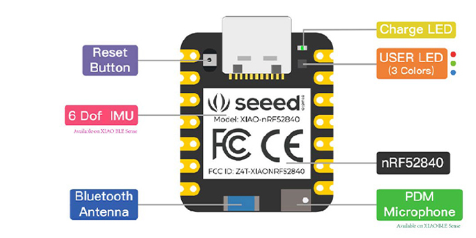
I've been doing a lot of work on my AAAudio library lately in regards to nRF52 devices like the XIAO BLE SENSE 52840 or the Feather Express 52840, and just added support for the onboard SAADC. This allows users to capture input audio from a regular analog microphone instead of requiring I2S or PDM. 

After having developed support for PDM, PWM and I2S, this wasn't too complicated. I've grown to understand the nRF52 interface, which is really nice and user friendly, and the documentation is great.


To use the SAADC interface start up analog audio by calling the following:

aaAudio.dinPin = 1; //Where 1 represents the AIN0, 2 represents AIN1, etc...
aaAudio.begin(3, 1); // Where 3 represents enabling of SAADC, 1 is for PWM output


All in all the SAADC seems to work very well! I am still doing initial testing & code review, but the changes have been pushed to GitHub as usual. Users can install from ZIP to test out the new code, or wait until the next release.

Saturday

AutoAnalogAudio: Decoding and playing MP3 files direct from SD card on nRF52

AutoAnalogAudio: Decoding and playing MP3 files direct from SD card on nRF52

Having fun with nRF52840 devices

I've been playing around quite a bit with my AnalogAudioAudio library since I got it working with I2S, including creating a simple Bluetooth controlled audio player.

Today, I found a simple MP3 decoding library, and decided to test it out. It actually worked! Now I have mp3 files being decoded directly from SD card on nRF52 devices like the Adafruit Feather 52840 or XIAO BLE Sense 52840.

There is lag of a few seconds prior to playback starting, but once that takes place, it seems to play the files well. The code I am using is still in prototyping stages but it does function!


I had to edit an existing MP3 decoding library a bit, but the current code I am using is at https://github.com/TMRh20/microDecoder

Any users that want to test it out can install directly from ZIP from this repository.

I would recommend testing the AutoAnalogAudio library with WAV files before venturing into MP3 playback, but to each his own...

Some example code using the above library is shown below. It has some bugs & quirks, but it does function.

#include <SD.h>
#include <AutoAnalogAudio.h>
#include "mp3.h"  // decoder
#include "pcm.h"

mp3 MP3;
pcm audio;
AutoAnalog aaAudio;

const char* audioFilename = "noceil.mp3";
uint8_t SD_CS_PIN = 5;                      // Set this to your CS pin for the SD card/module
#define USE_I2S 1

char songName[64];
float volumeControl = 0.2;
#define AUDIO_BUFFER_SIZE 6400

void setup() {

  pinMode(9, OUTPUT);
  digitalWrite(9, HIGH);
  pinMode(6, OUTPUT);  //Connected to SD pin of MAX98357A
  digitalWrite(6, HIGH);

  Serial.begin(115200);
  while (!Serial) delay(10);

  Serial.print("Init SD card...");
  if (!SD.begin(SD_CS_PIN)) {
    Serial.println("init failed!");
    return;
  }
  Serial.println("SD init ok");

  //aaAudio.I2S_PIN_LRCK = 28;  // Use different LRCK pin for Feather Express 52840
  aaAudio.maxBufferSize = AUDIO_BUFFER_SIZE;
  aaAudio.begin(0, 1, USE_I2S);

  playAudio(audioFilename);
}

void loop() {
 
  loadBuffer();

  // Control via Serial for testing
  if (Serial.available()) {
    char c = Serial.read();
    if (c == '=') {
      volumeControl += 0.1;
    } else if (c == '-') {
      volumeControl -= 0.1;
      volumeControl = max(0.0, volumeControl);
    } else if (c == 'p') {
      playAudio("waitress.mp3");
    }
    Serial.println(volumeControl);
  }

}


File myFile;

void playAudio(const char* audioFile) {

  if (myFile) {
    myFile.close();
    MP3.end();
  }
  //Open the designated file
  myFile = SD.open(audioFile);

  MP3.begin(myFile);
  MP3.getMetadata();
  aaAudio.setSampleRate(MP3.Fs, 1);
  Serial.println(MP3.Fs);
  aaAudio.dacBitsPerSample = MP3.bitsPerSample;
  Serial.println(MP3.bitsPerSample);
}

void loadBuffer() {

  if (myFile.available() > AUDIO_BUFFER_SIZE) {
    uint32_t sampleCounter = 0;
    for (uint32_t i = 0; i < 100; i++) {
      audio = MP3.decode();
      memcpy(&aaAudio.dacBuffer16[sampleCounter], audio.interleaved, 128);  // 128 bytes
      sampleCounter += 64;                                                  // 64 samples per go
    }
    for (uint32_t i = 0; i < 6400; i++) {
      int16_t sample = aaAudio.dacBuffer16[i];
      sample *= volumeControl;
      aaAudio.dacBuffer16[i] = sample;
    }
    aaAudio.feedDAC(0, 6400);
  } else {
    myFile.seek(0);
  }
}


Tuesday

AutoAnalogAudio Library: New examples for nRF52x including a BLE controlled Audio Player

 AutoAnalogAudio Library Updates for nRF52x:

 New examples for nRF52x & a BLE controlled Audio Player

With recent updates to the AutoAnalogAudio library, I've been able to put together a bunch of examples specific to the nRF52x platforms. The examples range from examples that use the onboard PDM microphone capabilities and either an I2S or Analog (PWM output) amplifier to a BLE controlled Audio Player.


The examples also demonstrate usage of the radio capabilities as well, using the radio either at a low level (nrf_to_nrf library), capable of streaming very high-quality audio or using BLE control to playback audio from SD card. 

When recording via PDM and either re-playing to an amplifier or broadcasting via radio, fairly high sample-rates can be used along with 16-bit modes, making for very decent quality wireless audio. There are some limitations when reading from SD card, as it seems the max SPI speed on these devices isn't that fast, so users need to play around with sample rates, stereo/mono modes and 8 or 16-bit samples.

Once the AutoAnalogAudio library is installed, the nRF52x examples can be found in Arduino examples under AutoAnalogAudio/Platforms/NRF52

XIAO BLE Sense 52840 used for testing


The BLE controlled audio player uses a bunch of different peripherals and pushes the capabilities of the device a bit, but it seems to work great. I've created another example using the Adafruit Bluefruit library as well, which supports faster SD reading & higher quality playback, which I will also include in the library soon. 

Here is the current code using the standard Arduino BLE library:

/* Arduino BLE control
led Audio Player for nRF52

 *
 * This is an example of me playing around with BLE control and different
 * services/characteristics to test the AutoAnalogAudio library.
 *
 * Requirements:
 * 1. nRF52 Device (Tested on nRF52840)
*  2. SD Card with WAV files: 8-bit, 16-24kHz, Mono
 * 3. I2S or Analog Amplifier + Speaker connected
 * 4. Mobile device or 'other' with nRF Connect installed
 *
 * Connect via nRF Connect App:
 * 1. Device should come up as BLE Audio Player
 * 2. You should see:
 *   a: Common Audio
*    b: Audio Input Type:
      Send a UTF-8 String to play a file: myfileDirectory/myfilename.wav
 *   c: Audio Input Control Point:
      Send an Unsigned value between 0-10 to set the volume low-high
 */


#include <SPI.h>
#include <SD.h>
#include <ArduinoBLE.h>
#include <AutoAnalogAudio.h>

AutoAnalog aaAudio;

/************** USER CONFIG ***********/
// File to play on startup
const char* audioFilename = "far8b16k.wav";  // 8-bit @ 24kHz audio is the max over SD card while BLE is running
uint8_t SD_CS_PIN = 2;                       // Set this to your CS pin for the SD card/module
#define USE_I2S 1                            // Set this to 0 for analog (PWM) audio output instead of I2S

/*********************************************************/
/* Tested with MAX98357A I2S breakout
/* BCLK connected to Arduino D1 (p0.03)
/* LRCK connected to Arduino D3 (p0.29)
/* DIN  connected to Arduino D5 (p0.05)
/* SD   connected to Arduino D6 (p1.11)
/*********************************************************/

#define FILENAME_BUFFER_LENGTH 64
char songName[FILENAME_BUFFER_LENGTH];
float volumeControl = 0.2;
#define AUDIO_BUFFER_SIZE 1600

BLEService audioService("1853");

// BLE Audio Charactaristic
BLECharacteristic audioDataCharacteristic("2b79", BLERead | BLEWrite | BLENotify, FILENAME_BUFFER_LENGTH);
BLEByteCharacteristic audioVolumeCharactaristic("2b7b", BLERead | BLEWrite);

void setup() {
  Serial.begin(115200);
  while (!Serial) delay(10);

  aaAudio.begin(0, 1, USE_I2S);  //Setup aaAudio using DAC and I2S or PWM

  // BLE initialization
  if (!BLE.begin()) {
    Serial.println("Starting BLE failed!");
    while (1) {};
  }

  BLE.setLocalName("BLE Audio Player");
  BLE.setAdvertisedService(audioService);

  audioService.addCharacteristic(audioDataCharacteristic);
  audioService.addCharacteristic(audioVolumeCharactaristic);
  BLE.addService(audioService);

  BLE.advertise();
  Serial.println("BLE Peripheral is now advertising");

  Serial.print("Init SD card...");
  if (!SD.begin(SD_CS_PIN)) {
    Serial.println("init failed!");
    return;
  }
  Serial.println("SD init ok");
  pinMode(6, OUTPUT);  //Connected to SD pin of MAX98357A
  digitalWrite(6, HIGH);

  playAudio(audioFilename);
}

void loop() {

  BLEDevice central = BLE.central();

  if (central) {

    if (central.connected()) {
      if (audioDataCharacteristic.written()) {
        memset(songName, 0, sizeof(songName));
        audioDataCharacteristic.readValue((uint8_t*)songName, FILENAME_BUFFER_LENGTH);
        playAudio(songName);
        Serial.println(songName);
      }
      if (audioVolumeCharactaristic.written()) {
        uint8_t vol;
        audioVolumeCharactaristic.readValue(vol);
        volumeControl = vol / 10.0;
        Serial.print("BLE Set Volume: ");
        Serial.println(volumeControl);
      }
    }
  }

  loadBuffer();

  // Control via Serial for testing
  if (Serial.available()) {
    char c = Serial.read();
    if (c == '=') {
      volumeControl += 0.1;
    } else if (c == '-') {
      volumeControl -= 0.1;
      volumeControl = max(0.0, volumeControl);
    } else if (c == 'p') {
      playAudio("brick/brick24.wav");
    }
    Serial.println(volumeControl);
  }
}

/*********************************************************/
/* A simple function to handle playing audio files
/*********************************************************/

File myFile;

void playAudio(const char* audioFile) {

  if (myFile) {
    myFile.close();
  }
  //Open the designated file
  myFile = SD.open(audioFile);

  myFile.seek(22);
  uint16_t var;
  uint32_t var2;
  myFile.read(&var, 2);   // Get channels (Stereo or Mono)
  myFile.read(&var2, 4);  // Get Sample Rate
  aaAudio.setSampleRate(var2, var - 1);

  myFile.seek(34);
  myFile.read(&var, 2);  // Get Bits Per Sample
  aaAudio.dacBitsPerSample = var;

  myFile.seek(44);  //Skip past the WAV header
}

void loadBuffer() {

  if (myFile.available()) {

    if (aaAudio.dacBitsPerSample == 8) {
      myFile.read(aaAudio.dacBuffer, AUDIO_BUFFER_SIZE);
      for (uint32_t i = 0; i < AUDIO_BUFFER_SIZE; i++) {
        aaAudio.dacBuffer[i] *= volumeControl;
      }
      aaAudio.feedDAC(0, AUDIO_BUFFER_SIZE);
    } else {
      myFile.read(aaAudio.dacBuffer16, AUDIO_BUFFER_SIZE);
      for (uint32_t i = 0; i < AUDIO_BUFFER_SIZE / 2; i++) {
        int16_t sample = aaAudio.dacBuffer16[i];
        sample *= volumeControl;
        aaAudio.dacBuffer16[i] = (uint16_t)sample;
      }
      aaAudio.feedDAC(0, AUDIO_BUFFER_SIZE / 2);
    }

  } else {
    myFile.seek(44);
  }
}


Thursday

AutoAnalogAudio Library & I2S Output Now Working on nRF52840

 AutoAnalogAudio Library & I2S Output Now Working on nRF52840

Playing around with high quality audio on the XIAO Sense 52840

Its been a while since my last post regarding I2S audio on the nRF52840, but I finally got it working!

It came down to too small of buffer sizes, plus incorrect pins used for the MAX98357A breakout board. Now that the main problems are figured out, I have it working. There are still some issues with buffering, as there are small clicks or pops here or there throughout playback if the buffer sizes are too small.


To get it working with the current code from GitHub users need to enable I2S by calling the begin(); function a little differently:

aaAudio.begin(0, 1, 1);  //Setup aaAudio using DAC and I2S

This example enables the 'DAC' output using I2S within the AutoAnalogAudio library.

Valid sample rates have now been modified to standard sample rates: 16kHz, 24kHz, 32kHz & 44kHz. These are the only accepted sample rates.

I've decided to leave the PWM output as the default behavior since it is simpler in nature, gives good results and works OK with smaller buffer sizes. This is important when transmitting or receiving audio over radio link, since you need pretty large buffers with I2S.

Users can set the I2S pins prior to calling the begin() function for other boards that use different pins.

aaAudio.I2S_PIN_LRCK = 28;

Default Arduino Pin-Out for MAX98357A on XIAO Sense 52840:

BCLK: D1 (P0.03)

LRCK: D3 (P0.29)

DIN: D5 (P0.05)

SD Pin needs to be set HIGH for left output

GAIN: VIN

Use buffer sizes from 3200 to 6400 samples with higher sample rates / bit-rates.

Successful Tesla Coil Power Transfer Experiment

Successful Tesla Coil Power Transfer Experiment

Transferring usable current with a single conductor

Up today we have a fairly simple experiment involving two Tesla coils connected by a single conductor. 

This is a recreation of Nikola Tesla's famous experiment demonstrating the practicality of power transfer between two Tesla coils and how it is supposed to work.

As shown in the video below, the coils work similarly to two water pumps connected by a single pipe. The action in the first water pump directly affects the action of the second water pump, transferring physical power between the two. A Tesla coil works on similar principles, transferring useable electrical power between devices.

Most experiments I've seen involving Tesla coils just produce big sparks, play music or whatever else, rarely have I seen them used for power transfer. This demonstrates that power transfer between Tesla Coils is not limited by the inverse square law, the losses are more akin to that found in a standard transmission line.


The system works at any scale, so can be used for power transfer between large or small devices, as long as the system is tuned correctly. Small motors, bigger lights etc. can be run off a device that is working with higher power.

I tried to keep the components and wiring as simple as possible so it is easy to replicate the experiment and understand what each component does. I've conducted this same experiment with higher power, running motors and lights using many watts of power.

Good efficiency along with the effectiveness shown here can be obtained by using better components, but since we are transmitting power directly through a conductive medium, the losses in the system can be compared to that of a standard transmission line, with voltage and current dropping with relative distance to the receiving device.

As stated in the video, the entire system needs to be in resonance for this to work properly, so if attempting to transmit power via the earth (a good conductor), it would need to be brought into electrical resonance for the system to work on a wider scale. This would require a much bigger, more powerful and more precise system like the one Nikola Tesla was building at Wardenclyffe.

Tuesday

Monitoring an RF24/NRF52x Network Continued...

 Monitoring an RF24/NRF52x Network Continued...

Explaining the recent changes

So in my last blog post I noted the progress I made in automating and monitoring my radio network, and it has been super interesting. Due to the ongoing activities affecting my network, it has become more robust and functional than ever, with bug fixes and recent changes vastly improving functionality of the network.

The network uses the RF24Gateway & RF24Ethernet libraries to enable use of the RF24 & RF52 radios as standard Network Interface Cards (NICs), with full TCP/IP support. The system makes use of the HTTP & MQTT protocols for communication. This along with software like Home Assistant and/or Node Red allows full automation of the network, including the generation of graphs, charts and buttons/controls.

The obsessive hacker activity that has been going on for years has now finally stopped for an astounding few days! I'm not exactly sure what finally did it, but I can only assume this person reads my blog.

The following screenshot shows the results of the past few days now, with the tail-end of some interference lowering the results, but very promising none the less. This is 0.3 percent packet loss after a few days of monitoring on a network with 17-18 Mesh/Ethernet nodes and going up!


It is super nice to be able to test, monitor and operate these little radios the way they were intended, without constant bombardment and incoming packets from my neighbor. Due to recent changes and a lack of interference, my MQTT nodes are now staying connected to the server for a large number of hours instead of minutes, and because of this are more responsive and communicative than ever. All statistics are up from the norm and looking good! The below video shows the connection times for 10 MQTT nodes on my network.

The video below shows my 'activity monitor' in which 15 of my active nodes are reporting in every few seconds. They simply identify themselves and show that they are active. An inactive node will fall behind quickly, making it obvious it is not active as its bar will not move. The intent is simply to put extra load on the network and keep track of any nodes that are failing.

Interestingly enough, when I introduced the ability to change the channel the network operates on, a small number of nodes would fail when I activated this functionality. I've found the issues to be hardware related, as when adding capacitors or replacing the connecting wires and/or nodes themselves, the problems went away. It seems changing channels regularly is kind of hard on the devices. It requires them to be pretty sound hardware-wise. All in all its been a good few days for the radio network. Lets just hope this keeps up!


Sunday

Monitoring an RF24/NRF52x Network & Creating a Scanner with the XIAO 52840 Sense

Monitoring an RF24/NRF52x Network & Creating a Scanner with the XIAO 52840 Sense

Monitoring the data from a scanner and other sources in real-time


I've been trying automate analysis of the RF24/NRF52 communication stack lately and decided it was time to automate things to a degree further. I've setup a system using MQTT and a failover node in the network, so at any given time, I can switch my main RF24/RF52 network to a different channel for testing purposes. The results have been a bit interesting, with interference popping up on channels that appear clean for long periods of time, going away after I switch to a new channel... for a while.

I also leverage NodeRed, MQTT, and other methods to monitor the radio network. To put things in perspective, I am using TCP/IP over the radio network, using the NRF24 radios as a standard NIC, to test connectivity etc, so the radios are very busy, transmitting many 32-byte packets for every TCP/IP packet sent. The network layer handles routing, fragmentation/reassembly, and the mesh layer ensures nodes stay connected to the network even under adverse conditions.

Here is a couple pictures showing ping statistics for a RPi5 running RF24Gateway in close proximity to a very busy master node:


This last picture shows a clean channel with minimal interference over a long period of time.


The % success rate of pinging the RPi5 from the master node, showing 2.24% packet loss on a busy network after a couple hours after changing to a better channel:


This is with 17 RF42Ethernet and/or RF24Gateway nodes running on the network and communicating large MQTT messages typically every few seconds each, so I'd say that amount of packet loss is very much acceptable. The network runs on a variety of NRF24 modules as well as the newer NRF52x modules.

The following is a graph of how long each of 10 nodes stay connected to the MQTT server over the radio network before having to re-connect. This tends to happen when there is interference and/or the mesh breaks down a bit and needs to re-converge. In some cases, in good radio conditions, nodes stay connected up to 5 hours or longer. With a recent update to RF24Ethernet, nodes should now stay connected even longer!


You see, I was thinking that 17 nodes pumping out constant traffic might be a bit too much for a the mesh network, but the results of testing indicate that this is not the case. I've had more nodes on a single network in the past, but was doubting recent changes to the network and the network itself. Testing on separate channels shows that the mesh works great with this number of nodes, its just the interference causing problems, which would occur with any number nodes.

One good example is the following screenshot, you can see the RX Packets (user): 327 line. Since none of my nodes are sending RF24Mesh or RF24Network messages, this is just one more pretty good indicator that one of my neighbors has an affinity for RF24 programming and is constantly hitting my network with spam and garbage. There is a history of DOS attacks as well, which took advantage of limited functionality of the is_valid_address() function of RF24Network at the time, and continue in very limited fashion due to the simplicity and effectiveness of RF24Mesh. Its been going on for years, almost daily, and I just can't understand the obsession with trying to hack my radio network. Its for testing purposes and contains no useful data. 
For somebody who was able to study the RF24 stack and identify a quality DOS attack that required only one small radio and took down my whole network, why not do something constructive with those skills?


The following is a good example of interference on the network, with my main network experiencing massive interference, with a node about 1.5-meters from the master unable to establish connectivity for a long period of time. I'm not sure what creates this level of interference, but it seems most if not all of my nodes on the main testing network using channel 111 lost connectivity for this same period of time between 10:33pm and 12:18am Jun 28th to Jun 29th 2024.


With that, I've developed a scanner sketch for the XIAO NRF52840 Sense, since the radio has a feature to directly monitor RSSI levels, and it also has an option to monitor received packets separately. This is a little different from the scanner sketch included with the library, since it uses the RGB LEDs onboard to indicate signal strength in real time. It also outputs data for the Serial Plotter in the Arduino IDE, so you can see what is going on on a graph as well as the LED indicators.

The Scanner:

The images below show the Serial Plotter output in the Arduino IDE. Since I have a very busy master node, it is normal to see a fair number of 'RX 'packets. The 'Values' indicator shows the count of how often the radio received a signal with an RSSI better than -65dBm.


The scan in the pics are during normal mesh operation, with not much happening. When there is a large amount of interference the RSSI (green) line goes way up, communication is hindered, but the mesh nature of the system ensures that nodes re-converge around the master node in a short period of time after the interference stops. Testing shows the mesh is very stable and reliable at this point, with interference measured showing a direct correlation to the communication abilities of the mesh.

The Sketch:

The sketch is fairly simple, but very useful for pulling in data regarding noise and received packets on a given channel over time. 

The sketch is also available on GitHub here.

/*
* Single channel scanner for XIAO 52840 Sense
*
* Monitoring of a single channel using the built-in radio of the NRF52840
* Scans a single channel for noise using the RSSI measurement feature
* Can also listen for received packets
*
* Used for monitoring level of traffic and noise separately for a given RF24Mesh master node
* Default is RSSI level monitoring, uncomment USE_RX to enable monitoring of received packets also
*
* ** LED Indicators: **
* Blue: Minimal traffic,
* Green: Medium traffic, 15/100 signals > -65dBm
* Red: Heavy traffic,  25/100 signals > -65dBm
* Orange: Very heavy traffic, 35/100 signals > -65dBm
*
*/
#include "nrf_to_nrf.h"
#include <RF24Network.h>
#include <RF24Mesh.h>

/**********************************************************/
#define CHANNEL 3   // What channel to scan on
#define MIN_DBM 65  // The minimum RSSI (dBm) for counting signals. Higher value == greater sensitivity.
#define USE_RX      // Also listen for and count received packets
/**********************************************************/

// Set up nRF24L01 radio on SPI bus plus pins 7 & 8

nrf_to_nrf radio;
RF52Network network(radio);
RF52Mesh mesh(radio, network);

const uint8_t num_channels = 1;
uint8_t values = 0;
uint8_t valuesR = 0;

// LED Setup
void red() {
  digitalWrite(LED_BLUE, HIGH);
  digitalWrite(LED_RED, LOW);
  digitalWrite(LED_GREEN, HIGH);
}
void green() {
  digitalWrite(LED_BLUE, HIGH);
  digitalWrite(LED_RED, HIGH);
  digitalWrite(LED_GREEN, LOW);
}
void blue() {
  digitalWrite(LED_BLUE, LOW);
  digitalWrite(LED_RED, HIGH);
  digitalWrite(LED_GREEN, HIGH);
}
void orange() {
  digitalWrite(LED_BLUE, HIGH);
  digitalWrite(LED_RED, LOW);
  digitalWrite(LED_GREEN, LOW);
}

void setup(void) {
  Serial.begin(115200);
  Serial.println(F("\n\rRF24/examples/scanner/"));

  // Setup and configure rf radio
  mesh.setNodeID(0);
  mesh.begin(CHANNEL);
  radio.setAutoAck(false);
  radio.setCRCLength(NRF_CRC_DISABLED);
  radio.setAddressWidth(2);
  radio.setChannel(CHANNEL);
  radio.startListening();
}

const int num_reps = 100;  // Max 255

void loop(void) {

  // Clear measurement values
  values = 0;
  valuesR = 0;

  // Scan channel num_reps times
  int rep_counter = num_reps;
  while (rep_counter--) {

    if (radio.testCarrier(MIN_DBM)) {
      ++values;
    }
    delayMicroseconds(256);

#if defined USE_RX
    if (radio.available()) {
      radio.read(0, 0);
      valuesR++;
    }
#endif
    delayMicroseconds(256);
  }

  // Print out channel measurements
  Serial.print("Low:");
  Serial.println(15);
  Serial.print("Med:");
  Serial.println(25);
  Serial.print("High:");
  Serial.println(35);
  Serial.print("Values:");
  Serial.println(values);
  if (values >= 15 && values < 25) {
    green();
  } else if (values >= 25 && values < 35) {
    red();
  } else if (values >= 35) {
    orange();
  } else {
    blue();
  }
#if defined USE_RX
  Serial.print("RX:");
  if (valuesR) {
    Serial.println(valuesR);
  } else {
    Serial.println(0);
  }
#endif
}

Tuesday

RF24Mesh and RF24Network Enhancements

 RF24Mesh and RF24Network Enhancements

Libraries updated with better functionality

So we've been putting in a bunch of work lately on the RF24/NRF52x communication stack for Arduino, and surprisingly, given the age of the libraries, we were able to make a number of changes that significantly impact the performance of the network and mesh.

RF24Mesh:

1. Utilize all poll requests. 

The prior behavior of the mesh was to send out a poll request via multicast and gather the responses. Then the mesh layer would attempt to request an address via one of the nodes that responded to the poll. If this failed however, the node would continue on and send out another poll. The current behavior now utilizes up to 4 received poll responses and loops through them all until either failure or a successful address request is made before moving to the next multicast level and sending out another poll request.

2. Enhance the ability to verify connectivity

The prior behavior of the mesh was to call `getAddress(_nodeID);` and verify its own address with the master node. The call would fail if anything but a successful address response was received. Now there is some logic added to return immediately if the address is not found in the master list or is default. It will also return immediately if the nodes address has been zeroed out. Retries will take place if the request failed or timed out. Finally, the node actually verifies that the received address matches its own address.

Update: I am currently testing a new method of connection checking, where each node only contacts their parent node instead of the master node. This appears to reduce traffic, increase connection times, and improve the overall stability of the mesh.

It may not seem like much, but the changes should tend to reduce network traffic, while providing more seamless mesh operation.

RF24Network:

1. Fix error sending data

Per the RF24 documentation and behavior, when using some of the advanced write functions, there is a need to call `radio.txStandby()` if a write fails, otherwise the radio will essentially hang and all subsequent writes will fail. This was partially missed in RF24Network, so a call has been added when an auto-ack payload fails. This should improve reliability and consistency in sending data.

RF24:

1. Interrupt enhancements. 

The use of interrupts on Linux platforms like the Raspberry Pi has been greatly improved and no longer requires root access to operate. Unlike the RF24 library, the interrupt functionality uses GPIO pin numbers instead of BCM pin numbers. ie: Use GPIO 24 instead of pin 18.

RF24Ethernet

1. Fix re-transmit mechanism

The associated UIP IP stack incorporated with RF24Ethernet uses a retransmit mechanism when acks are not received etc, but it was not working. This is now fixed and results in much more reliable, longer connectivity with MQTT, HTTP and other protocols & applications that transmit data.


All in all its been a good year for the RF24/NRF52x communication stack, with support also recently added for Nordics NRF52x SOCs, there are so many potential ways these libraries can be configured! Encryption and authentication features are also available with the newer radio modules, which will easily handle audio streaming and more advanced functionality.

Auto Analog Audio & NRF52840: Now working on non-Mbed cores

 Auto Analog Audio & NRF52840: Now working on non-Mbed cores

Playing around with the AAAudio library

So I finally decided to make the necessary purchase and get myself a relatively cheap oscilloscope, and with that play around more with the AAAudio library. Even with the added view into the output signal and what is going on using the scope, I still haven't been able to figure out what I'm doing wrong with the I2S interface, so for now the audio is not of the highest quality, which is relatively good for voice, but not so good for higher frequency audio signals.

I have, however, made progress on using the non-MBED core for both input and output of audio using the PDM (microphone) and PWM (amp/speaker) interfaces, which opens up more of the capabilities of this device! In the end, once I actually quit working with the I2S interface, it wasn't that difficult getting the non-MBED core to work. This means that AAAudio should work on other devices like the Feather 52840 Express etc, but it hasn't been fully tested yet. The PWM interface can handle ~10-bit audio at 16Khz, and lower at higher sample rates.

It also allows users to adjust between 20khz and 16khz PDM samples now as well!

Users can specify which pins to use for PWM by editing the library src/NRF52840/AutoAnalogAudio.cpp file and specifying the GPIO pin and port numbers, else it defaults to GPIO #5, port 0 for output.

As of this writing, users would need to download and install the library from ZIP directly from here because I will not do a new release for a while. (Still testing and potentially updating the new capabilities)

Monday

Installing and using the RF24 Communication stack on Arduino and RPi - 2024

 Installing and using the RF24 Communication stack on Arduino and RPi - 2024


I made a video to demonstrate current installation and usage of the RF24 comm stack on Arduino and Linux using the latest available code.

See Arduino Project Hub for a text based tutorial


AutoAnalogAudio Library - nRF52 Now supports Successive Approximation Analog-to-Digital Converter for Audio Input

 AutoAnalogAudio Library - nRF52 Now supports SAADC Support for Successive Approximation Analog-to-Digital Converter for Audio Input I'v...